Students can Download Chapter 15 Communication Systems Notes, Plus Two Physics Notes helps you to revise the complete Kerala State Syllabus and score more marks in your examinations.
Kerala Plus Two Physics Notes Chapter 15 Communication Systems
Introduction
The aim of this chapter is to introduce the concepts of communication, namely the mode of communication, the need for modulation, production, and detection of amplitude modulation.
![]()
Elements Of A Communication System
Every communication system has three essential elements.
- Transmitter
- Medium/channel
- Receiver
The general form of a communication system is given below.

1. Transmitter:
A transmitter transmits the information after modifying it to a form, suitable for transmission.
Transducers:
Transducers is a device, which convert a physical quantity (called information) into electrical signal are known as transducers.
Examples:
microphone (convert sound into electrie signals), photodetector (convert light into electric signals) are the examples of transducers.
2. Medium/Channel:
Channel is the physical me-dium, which connects transmitter and receiver.
In the case of telephony, communication channel is the transmission lines. In radio communication (orwireless communication) the free space serves as the communication channel.
![]()
3. The receiver:
The receiver receives the transmitted signal. The received signal is converted to suitable form and deliver it to the user.
Modes of communication:
There are two basic modes of communication:
- point-to-point
- Broadcast
1. Point-to-Point:
In point-to-point communication mode, communication takes place over a link between a single transmitter and a receiver.
Example: Telephone communication
2. Broadcast:
In broadcast mode, there are a large number of receivers corresponding to a single transmitter.
Example: Radio and Television.
Basic Terminology Used In Electronic Communication Systems
It would be easy to understand the principles underlying any communication, if we get knowledge about the following basic terminology.
(i) Transducer:
Any device that converts one form of energy into another can be termed as a transducer.
(ii) Signal:
Information converted in electrical form and suitable for transmission is called a signal. Signals can be either analog or digital. Analog signals are continuous variations of voltage or current.
They are essentially single-valued functions of time. Sine wave is a fundamental analog signal. Sound and picture signals in TV are analog in nature.
Digital signals are those which can take only discrete step wise values. Binary system that is extensively used in digital electronics employs just two levels of a signal. ‘0’ corresponds to a low level and ‘1’ corresponds to a high level of voltage/current.
![]()
(iii) Noise:
Noise refers to the unwanted signals that disturb communication system.
(iv) Transmitter:
A transmitter processes message signal to make it suitable for transmission.
(v) Receiver:
A receiver extracts the desired message signals from the received signals.
(vi) Attenuation:
The loss of strength of a signal while propagating through a medium is known as attenuation.
(vii) Amplification:
It is the process of increasing the amplitude of a signal using an electronic circuit called the amplifier.
(viii) Range:
It is the largest distance between a source and a destination up to which the signal is received with sufficient strength.
(ix) Bandwidth:
Bandwidth refers to the frequency range over which an equipment operates.
(x) Modulation:
The original low frequency message signal cannot be transmitted to long distances because of reasons given in Section 15.7. Therefore, the low frequency message signal is superimposed on a high frequency wave, (which acts as a carrier of the information). This process is known as modulation.
(xi) Demodulation:
The process of retrieval of information from the carrier wave is termed demodulation. This is the reverse process of modulation.
(xii) Repeater:
A repeater is a combination of a receiver and a transmitter. A repeater, picks up the signal from the transmitter, amplifies and retransmits it to the receiver.
Repeaters are used to extend the range of a communication system as shown in figure. A communication satellite is essentially a repeater station in space.
![]()
Bandwidth Of Signals
The bandwidth of a message signal refers to a band of frequencies, which are necessary for transmission of the information contained in the signal.
The band Of 2800 Hz (300 Hz – 3100 Hz) is enough to transmit speech signals. To transmit music, 20 KHz. band width is required (because of the high frequencies produced by the musical instruments).
Bandwidth of square wave:
A rectangular wave can be decomposed into a superposition of sinusoidal waves of frequencies ν0, 2ν0, 3ν0, 4ν0………nν0, where n is an integer extending to infinity.

To produce a rectangular wave, we need to super impose all the harmonics ν0, 2ν0, 3ν0, ………nν0, which implies that bandwidth required for the transmission of rectangular wave is infinite.
For practical purpose, the higher harmonicas are removed. Thus bandwidth is limited. The removal of higher harmonics dos not effect the shape of rectangular wave. Because the contribution of higher harmonics to rectangular wave form is less.
![]()
Bandwidth Of Transmission Medium
Different types of transmission media offer different bandwidths. The commonly used transmission media are wire, free space and fiber optic cable.
Cable offers a bandwidth of 750MHz Optical fibre offers a bandwidth of 1 THz to 1000 THz (Microwaves to ultraviolet).
Propagation Of Electro Magnetic Waves
When the em wave travels through space, the strength of wave decreases.
1. Ground wave:
It is a mode of propagation in which the ground waves progress along the surface of the earth. As the groundwave passes over the surface of the earth, it is weakened as a result of the energy absorption by the surface.
Due to this loss the ground waves are not suited for very large range communication. The ground wave propagation is effective only in very low frequencies (VLF) 500 KHz to 1500 KHz.
2. Sky waves:
It is that mode of wave propagation in which the radiowaves emitted from the transmitting antenna reach the receiving antenna after reflection in the ionosphere.

![]()
The UV and other high energy radiations coming from sun are absorbed by air molecules. Due to this absorption, the air molecules get ionized and form an ionized layer of electrons and ions around the earth. The ionosphere extends from a height of nearly 80 Km to 300 km above the earth’s surface.
Explanation for reflection of em wave:
The refractive index of ionosphere decreases as we go into the ionosphere. Therefore an em wave coming from ground undergoes fortotal internal reflection.
Since this phenomenon is a frequency dependent one, there is a critical frequency (ranges from 5 to 10 MHz) above which the wave incident on the ionosphere will not reflect back. Therefore, sky wave propagation is not possible above 10 MHz. This limitation is overcome with satellite communication.
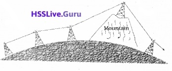
3. Space wave:
A space wave travels in a straight line from transmitting antenna to the receiving antenna. Space wave communication is also called Line of sight (LOS) communication.
Because of line-of-sight nature of propagation, direct waves get blocked at some point by the curvature of the earth as illustrated in the above figure.
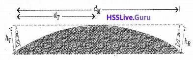
If the signal is to be received beyond the horizon then the receiving antenna must be high enough to receive the line-of-sight waves.
The maximum line-of-sight distance dM between the two antennas having heights hT and hR above the earth is given by
dm = \(\sqrt{2 R h_{T}}+\sqrt{2 R h_{R}}\)
Note:
At frequencies above 40 MHz, communication is essentially limited to line-of-sight paths. At these frequencies, the antennas are relatively smaller.
![]()
Modulation And Its Necessity
1. Size of the antenna or aerial:
For transmitting and receiving signal we need antenna having a size comparable to the wavelength of the signal (should have length at least one quarter of the wavelength).
Therefore, to transmit a 1 KHz signal it requires about 500m long antenna, which is practically impossible. This demand that the audio signal is to be converted into a high frequency signal fortransmission.
2. Effective power radiated by an antenna:
To send signals to large distances the power of the transmitter should be as high as possible. Transmission power of an antenna is inversely proportional to the square of the wavelength (P α (l/λ)2). Therefore, to attain high radiation power the wavelength should be as small as possible.
3. Mixing up of signals from different transmitters:
Suppose many people are talking at the same time and those audio signals are transmitting simultaneously. All those signals will get mixed up and there is no way to distinguish between them. This problem can be solved by transmitting the audio signals in the form of high frequency signals.
Modulation:
To overcome all those difficulties (mentioned above) we make use of the technique called modulation. Modulation is the process of super posing a low frequency (audio signal) information on to a high frequency carrier wave.
Carrierwave:
The carrierwave may be sinusoidal wave ora pulse train.

![]()
Sinusoidal carrier wave can be mathematically expressed
c(t) = Ac sin (ωct + Φ)
where c(t)is the signal strength (voltage or current). Ac is the amplitude, ωc (2πvc) is the angular frequency and Φ is the initial phase of the carrier wave.
While modulating, any one of the parameters is varied according to the base band signal (audiosignal). These result in three types of modulation using sinusoidal carrier waves namely
- Amplitude modulation
- Frequency modulation
- Phase modulation

In a similar way, a pulse train is characterized by pulse amplitude, pulse duration or pulse width and pulse position denoted by the rise and falls of the pulse. Hence different types of pulse modulation are
- Pulse Amplitude Modulation (PAM)
- Pulse Width Modulation (PWM)
- Pulse Position Modulation (PPM)
![]()
Amplitude Modulation
In amplitude modulation the amplitude of the carrier is varied in accordance with the information signal.
Mathematical analysis:
Consider a sinusoidal carrier wave c(t)=Ac sinωct and a modulating signal (message signal) m(t) = Am sinωmt.
The message signal is added in such a way to change the amplitude of carrier wave. Hence the modulated signal can be written as,
cm(t) = (Ac + Am sinωm t) sinωct
= Ac sinωc t + Am sinωm t sinωc t
= Ac sinωc t + µ Ac sinωc t sinωm t
where

called modulation index.
Using trigonometric relation sinAsinB = 1/2cos(A – B) – cos(A + B) we can write
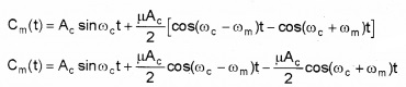
The above equation shows that, the modulated signal consists of three frequencies, ωc, (ωc – ωm), (ωc + ωm) where (ωc – ωm ) is called lower side band frequency and (ωc + ωm) is called upper side band frequency.
A plot of Ac with ω for AM signal:
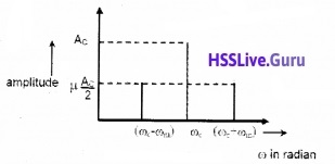
Note:
Modulation index (µ) is always kept ≤1 to avoid distortion.
![]()
Production Of Amplitude Modulated Wave
Production of an amplitude-modulated wave is given in a block diagram.
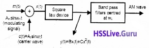
Step – I:
The modulating signal Amsinωmt is added to the carrier signal Acsinωct to produce x(t).
x(t)=Am sinωm t + Ac sinωc t……..(1)
Step – II:
This signal x(t) = Amsinωmt + Acsinωct is passed through a square law device which is a non-linear device which produces an output.
y(t) = B x(t) + C x(t)2………..(2)
where B and C are constants.
Substitute the eq(1) in eq.(2).
y(t) = B [Am sinωmt + Acsinωct] + C [Am sinωmt + Ac sinωct]2
y(t) = B Am sinωmt + B Acsinωc + C [A2m sin2ωm t + A2c sin2ωct + 2AmAc sinωct sinωmt]
Step – III:
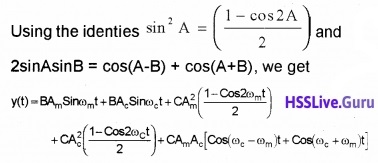
The output from the square law device y(t) is passed to Band pass filter. The Band pass filter remove dc component \(\frac{c}{2}\)(A2m + A2c) and ωm, 2ωm, and 2ωc from the signal y(t).
Hence the output of band bass filter will be amplitude modulated wave containing three frequencies ωc, (ωc – ωm) and (ωc + ωm). ie. Output of band pass filter
= BAωc sinωc t + C AmAc (cos(ωc – ωm )t) + AmAc(cos(ωc + ωm)t)
The output contain three frequencies ωc, (ωc – ωm) and (ωc + ωm).
Transmission of AM wave:
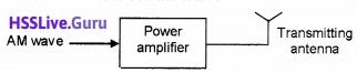
The AM is given to a power amplifier. The power amplifier provides the necessary power and then the modulated signal is fed to an antenna for radiation.
![]()
Detection Of Amplitude Modulated Wave
The block diagram of AM receiver is shown in figure.
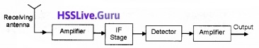
Step I:
The AM wave is received by the Receiving antenna.
Step II:
The signal from the antenna is given to the amplifier. The amplifier will give sufficient strength to the receiving signal.
Step III:
The output from the amplifier is given to the IF (intermediate frequency) stage. In IF stage, the carrier frequency is changed into a lower frequency.
Step IV:
Detection:
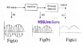
The output from the IF stage is given to the detector. Detection is the process of recovering the modulating signal from the modulated carrier wave. The process of detection is shown in block diagram.
The modulated signal fig (a) is given to the rectifier. The rectifier removes the negative part of the A.M and gives the output as shown in figure (b). This output is given to the envelop detector. The envelop detector gives an output of message signal as shown in figure (c).
![]()
Step V:
The message signal from the detector is given to the amplifier. The amplifier, amplifies the signal and given to the loud speaker.