Students can Download Chapter 3 Current Electricity Notes, Plus Two Physics Notes helps you to revise the complete Kerala State Syllabus and score more marks in your examinations.
Kerala Plus Two Physics Notes Chapter 3 Current Electricity
Introduction
In the present chapter, we shall study some of the basic laws concerning steady electric currents.
Electric Current
Rate of flow of electric charge is called electric current. or

Electric Currents In Conductors
- Conductors: Free electrons are found in conductors. The electric current in conductors is due to the flow of electrons.
- Electrolytes: The current in electrolyte is due to flow of ions.
- Semiconductor: The current in semiconductor is due to flow of both holes and electrons.
![]()
Ohm’s Law
At constant temperature, the current through a conductor is directly proportional to the potential difference between its ends.
V α I (or)
![]()
where R is constant, called resistance of materials.
1. Resistance of a material:
Factors Affecting Resistance of Resistor:
For a given material resistance is directly proportional to the length and inversely proportional to the area of cross-section.
R ∝ \(\frac{\mathrm{L}}{\mathrm{A}}\)

where ρ is the constant of proportionality and is called resistivity of material.
Resistivity (coefficient of specific resistance) of a Material:
The resistance per unit length for unit area of cross-section will be a constant and this constant is known as the resistivity of the material. The resistivity or coefficient of specific resistance is defined as the resistance offered by a resistor of unit length and unit area of cross-section.

Resistivity is a scalar quantity and its unit is Ω-m.
Conductance and conductivity:
The reciprocal of resistance is called conductance and the reciprocal of resistivity is called conductivity. The SI unit of conductance is seimen and that for conductivity is seimen per meter. The unit of conductance can also be expressed as Ω-1.
![]()
Current density: Current per unit area is called current density
current density j = \(\frac{I}{A}\)
Vector form
![]()
Mathematical expression of Ohm’s law in terms of j and E:
Considers conductor of length i. Let V’ be the potential difference between the two ends of a conductor.
According to ohms law
We know V= IR

This potential difference produces an electric field E in the conductor. The p.d. across the conductor also can be written as
V = El _____(2)
Comparing (1) and (2), we get
El = jρl
E = jρ
The above relation can be written in vector form as

where σ is called conductivity of the material.
![]()
Drift Of Electrons And The Origin Of Resistivity
Random thermal motion of electrons in a metal:
Every metal has a large number of free electrons. Which are in a state of random motion within the conductor. The average thermal speed of the free electrons in random motion is of the order of 105m/s.
Does random thermal motion produce any current? The directions of thermal motion are so randomly distributed. Hence the average thermal velocity of the electrons is zero. Hence current due to thermal motion is zero.
(a) Drift Velocity (vd):
The average velocity acquired by an electron under the applied electric field is called drift velocity.
Explanation: When a voltage is applied across a conductor, an electric filed is developed. Due to this electric field electrons are accelerated. But while moving they collide with atoms, lose their energy and are slowed down. This acceleration and collision are repeated through the motion. Hence electrons move with a constant average velocity. This constant average velocity is called drift velocity.
(b) Relaxation time (τ):
Relaxation time is the average of the time between two successive collisions of the free electrons with atoms.
(c) Expression for drift velocity:
Let V be the potential difference across the ends of a conductor. This potential difference makes an electric field E. Under the influence of electric field E, each free electron experiences a Coulomb force.
F = -eE
or ma = -eE
a = \(\frac{-e E}{m}\) _____(1)
Due to this acceleration, the free electron acquires an additional velocity. A metal contains a large number of electrons.
For first electron, additional velocity acquired in a time τ,
v1 = u1 + aτ1
where u1 is the thermal velocity and τ is the relaxation time.
Similarly the net velocity of second, third,……electron
![]()
v2 = u2 + aτ2
v3 = u3 + aτ3
vn = un + aτn
∴ Average velocity of all the ‘n’ electrons will be

Vav = 0 + aτ (∴ average thermal velocity of electron is zero)
where τ = \(\frac{\tau_{1}+\tau_{2}+\ldots \ldots \ldots+\tau_{n}}{n}\)
where Vav is the average velocity of electron under an external field. This average velocity is called drift velocity.
ie. drift velocity Vd = aτ _____(2)

(d) Relation between electric current and drift speed:
Consider a conductor of cross-sectional area A. Let n be the number of electrons per unit volume. When a voltage is applied across a conductor, an electric filed is developed. Let vd be the drift velocity of electron due to this field.
Total volume passed in unit time = Avd
Total number of electrons in this volume = Avdn
Total charge flowing in unit time=Avdne
But charge flowing per unit time is called current I ie. current, I = Avdne
I = neAvd
Now current density J can be written as
J = nevd (J= I/A)
Deduction of Ohm’s law: (Vector form)
We know current density
J = nvde

![]()
1. Mobility: Mobility is defined as the magnitude of the drift velocity per unit electric field.

Limitations Of Ohm’s Law
Certajn materials do not obey Ohm’s law. The deviations of Ohm’s law are of the following types.
1. V stops to be proportional to I.

Metal shows this type behavior. When current through metal becomes large, more heat is produced. Hence resistance of metal increases. Due to increase in resistance the V-I graph becomes nonlinear. This nonlinear variation is shown by solid line in the above graph.
2. Diode shows this type behavior. We get different values of current for same negative and positive voltages.

![]()
3. This type behavior is shown by materials like GaAs. there is more than one value of V for the same current I.

Note: The materials which donot obey ohms law are mainly used in electronics.
Resistivity Of Various Materials
The materials are classified as conductors, semi conductors, and insulators according to their resistivities. Commercially produced resistors are of two types.
- Wire bound resistors
- Carbon resistors
1. Wire bound resistor:
Wire wound resistors are made by winding the wires of an alloy.
Eg: Manganin, Constantan, Nichrome.
2. Carbon resistors:
Resistors in the higher range are made mostly from carbon. Carbon resistors are compact. Carbon resistors are small in size. Hence their values are given using a colourcode.
(i) Colourcode of resistors:
The resistance value of commercially available resistors are usually indicated by certain standard colour coding.
The resistors have a set of coloured rings on it. Their significance is indicated in the table The first two bands from the end indicated the first two significant digits and the third band indicates the decimal multiplier. The last metallic band indicates the tolerance.
Value of colours:

![]()
Illustration:

The colour code indicated in the given sample is Red, Red, Red with a silver ring at the right end. Then the value of given resistance is 22 × 102 ±10%.
Temperature Dependence Of Resistivity:
The resistivity of a material is found to be dependent on the temperature. The resistivity of a metallic conductor is approximately given by,
ρT = ρo[1 + α(T – To)]
where ρT is the resistivity at a temperature T and ρo is the resistivity at temperature To. α is called the temperature coefficient of resistivity.
Variation of resistivity in metals:

The temperature coefficient (α) of metal is positive. Which means resistivity of metal increases with temperature. The variation of resistivity of copper is as shown in above figure.
Eg: Silver, copper, nichrome, etc.
Variation of resistivity in semi conductor:

The temperature coefficient (α)of semiconductor is negative. Which means that resistivity decreases with increase in temperature. The variation of resistivity with temperature for a semiconductor is shown in above figure.
Eg: Carbon,Germanium,silicon
Variation of resistivity in standard resistors:

![]()
standard resistors, the variation of resistivity will be very little with temperatures. The variation of resistivity with temperature for standard resistors is show above.
Eg: Manganin and constantan.
Explanation for the variation of resistivity:
The resistivity of a material is given by

The above equation shows that, resistivity depends inversely on number density and relaxation time τ.
Metals:
Number density in metal does not change with temperature. But average speed of electrons increases. Hence frequency of collision increases. The increase in frequency of collision decreases the relaxation time τ. Hence the resistivity of metal increases with temperature.
Insulators and semiconductors:
For insulators and semiconductors, the number density n increases with temperature. Hence resistivity decreases with temperature.
Electrical Energy, Power
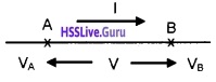
Consider two points A and B in a conductor. Let VA and VB be the potentials at A and B respectively. The potential At A is greater than that B and difference in potential is V.
If ∆Q charge flows from A to B in time ∆t. The potential energy of charge will be decreased. The decrease in potential energy due to charge flow from A to B,
= VA∆Q – VB∆Q
= (VA – VB)∆Q
= V∆Q (VA – VB = V)
This decrease in PE appeared as KE of flowing charges. But we know, the kinetic energy of charge carriers do not increase due to the collisions with atoms. During collisions, the kinetic energy gained by the charge carriers is shared with the atoms.
Hence the atoms vibrate more vigorously ie. The conductor heats up. According to conservation of energy, heat developed in between A and B in time ∆t
∆H = decrease in potential energy
∆H = V∆Q
∆H = VI∆t (∵ ∆Q=I∆t)
\(\frac{\Delta \mathrm{H}}{\Delta \mathrm{t}}\) = VI
Rate of workdone is power, ie
![]()
![]()
using Ohm’s law V = IR

It is this power which heats up the conductor.
Power transmission:
The electric power from the electric power station is transmitted with high voltage. When voltage increases, the current decreases. Hence heat loss decreases very much.
Combination Of Resistors – Series And Parallel Combination
Resistors in series:
Consider three resistors R1, R2 and R3 connected in series and a pd of V is applied across it.

In the circuit shown above the rate of flow of charge through each resistor will be same i.e. in series combination current through each resistor will be the same. However, the pd across each resistor are different and can be obtained using ohms law.
pd across the first resistor V1 = I R1
pd across the second resistor V2, = I R2
pd across the third resistor V3 = I R3
If V is the effective potential drop and R is the effective resistance then effective pd across the combination is V = IR
Total pd across the combination = the sum pd across each resistor, V = V1 + V2 + V3
Substituting the values of pds we get IR = IR1 + IR2 + IR3
Eliminating I from all the terms on both sides we get
![]()
Thus the effective resistance of series combination of a number of resistors is equal to the sum of resistances of individual resistors.
![]()
1. Resistors in parallel:
Consider three resistors R1, R2 and R3 connected in parallel across a pd of V volt. Since all the resistors are connected across same terminals, pd across all the resistors are equal.

As the value of resistors are different current will be different in each resistor and is given by Ohm’s law
Current through the first resistor
I1 = \(\frac{V}{R_{1}}\)
Current through the second resistor
I2 = \(\frac{V}{R_{2}}\)
Current through the third resistor
I3 = \(\frac{V}{R_{3}}\)
Total current through the combination is
I = \(\frac{V}{R}\), where R is the effective resistance of parallel combination.
Total current through the combination = the sum of current through each resistor
I = I1 + I2 + I3
Substituting the values of current we get

Eliminating V from all terms on both sides of the equations, we get

Thus in parallel combination reciprocal of the effective resistance is equal to the sum of reciprocal of individual resistances. The effective resistance in a parallel combination will be smaller than the value of smallest resistance.
![]()
Cells, Emf, Internal Resistance
Electrolytic cell:
Electrolytic cell is a simple device to maintain a steady current in an electric circuit. A cell has two electrodes. They are immersed in an electrolytic solution.
E.M.F:
E.M.F. is the potential difference between the positive and negative electrodes in an open circuit. ie. when no current is flowing through the cell.
Voltage:
Voltage is the potential difference between the positive and negative electrodes, when current is flowing through it.
Internal resistance of cell:
Electrolyte offers a finite resistance to the current flow. This resistance is called internal resistance (r).
Relation between ε, V and internal drop:
Consider a circuit in which cell of emfs is connected to resistance R. Let r be the internal resistance and I be the current following the circuit.
According to ohms law,
current flowing through the circuit

V is the voltage across the resistor called terminal voltage. Ir is potential difference across internal resistance called internal drop.
![]()
Cells In Series And Parallel

Consider two cells in series. Let ε1, r1 be the emf and internal resistance of first cell. Similarly ε2, r2 be the emf and internal resistance of second cell. Let I be the current in this circuit.
From the figure, the P.d between A and B
VA – VB = ε1 – Ir1 _____(1)
Similarly P.d between B and C
VB – VC = ε2 – Ir2 ______(2)
Hence, P.d between the terminals A and C
VAC = VA – VC = VA – VB + VB – VC
VAC = [VA – VB] + [VB – VC]
when we substitute eqn. (1) and (2) in the above equation.
VAC = ε1 – Ir1 + ε2 – Ir2 VAC = (ε1 – ε2) – I(r1 + r2)
VAC = εeq – Ireq
where εeq = ε1 + ε2, and req = r<sub1 + r2
The rule of series combination:
- The equivalent emf of a series combination of n cells is the sum of their individual emf.
- The equivalent internal resistance of a series com-bination of n cells is just the sum of their internal resistances.
Cells in parallel:

Consider two cells connected in parallel as shown in figure. ε1, r1 be the emf and internal resistance of first cell and ε2, r2 be the emf and internal resistance of second cell. Let I1 and I2 be the current leaving the positive electrodes of the cells.
Total current flowing from the cells is the sum of I1 and I2.
ie. I = I1 + I2 ______(1)
Let VB1 and VB2 be the potential at B1 and B2 respectively. Considering the first cell, P.d between B1 and B2.

Considering the second cell, P.d between B1 and B2

![]()
Substituting the values I1 and I2 in eq.(1), we get


If we replace the combination by a single cell between B1 and B2, of emf and εeq and internal resistance req, we have
V = εeq – Ireq ______(3)
The eq(2) and eq(3) should be same.

The above equation can be put in a simpler way.

If there are n cells of emf ε1, ε2,………..εn and internal
resistance r1, r2………..rn respectively, connected in parallel.

Kirchoff’s Rules
1. First law (Junction rule): The total current entering the junction is equal to the total current leaving the junction.
Explanation:

![]()
Consider a junction ‘O’. Let I1 and I2 be the incoming currents and I1, I4 and I5 be the outgoing currents.
According to Kirchoff’s first law,
![]()
2. Second law (loop rule): In any closed circuit the algebraic sum of the product of the current and resistance in each branch of the circuit is equal to the netjemf in that branch.
OR
Total emf in a closed circuit is equal to sum of voltage drops

Explanation: Consider a circuit consisting of two cells of emf E1 and E2 with resistances R1, R2 and R3 as shown in figure. Current is flowing as shown in figure
Applying the second law to the closed circuit ABCDE1A.
-I3R3 + E1 + -I1R1 = 0
Similarly for the closed loop ABCDE2A.
-I2R2 + -I3R3 + E2 = 0
For the closed loop AE2DE1A
-I1R1 + I2R2 + -E2 + E1 = 0
Note:
- Voltage drop in the direction of current is taken as negative (and vice versa).
- emf is taken as positive, if we go -ve to +ve terminal (and vice versa)
![]()
Wheatstone’s Bridge
Four resistances P, Q, R, and S are connected as shown in figure. Voltage ‘V’ is applied in between A and C. Let I1, I2, I3 and I4 be the four currents passing through P, R, Q, and S respectively.

Working:
The voltage across R
When key is closed, current flows in different branches as shown in figure. Under this situation
The voltage across P, VAB = I1P
The voltage across Q, VBC = I3Q __(1)
The voltage across R, VAD = I2R
The voltage across S, VDC = I4S
The value of R is adjusted to get zero deflection in galvanometer. Underthis condition,
I1 = I3 and I2 = I4 _____(2)
Using Kirchoffs second law in loopABDA and BCDB, weget
VAB = VAD ______(3)
and VBC = VDC _______(4)
Substituting the values from eq(1) into (3) and (4), we get
I1P = I2R ______(5)
and I3Q = I4S _____(6)
Dividing Eq(5) by Eq(6)

[since I1 = I3 and I2 = I4]
This is called Wheatstone condition.
![]()
Meter Bridge
Uses: Meter Bridge is used to measure unknown resistance.
Principle: It works on the principle of Wheatstone bridge condition (P/Q=R/S).

Circuit details:
Unknown resistance X’ is connected in between A and B. Known resistance (box) is connected in between B and C. Voltage is applied between A and C. A100cm wire is connected between A and C. Let r be the resistance per unit length. Jockey is connected to ‘B’ through galvanometer.
Working: A suitable resistance R is taken in the box. The position of jockey is adjusted to get zero deflection.
If ‘l’ is the balancing length from A, using Wheatstone’s condition,

knowing R and l, we can find X (resistance of wire)
Resistivity: Resistivity of unknown resistance (wire) can be found from the formula
\(\rho=\frac{\pi r^{2} X}{l}\)
Where r (the radius of wire) is measured using screw gauge. l (the length of wire) is measured using meter scale
Note: Meter bridge is most sensitive when all the four resistors are of the same order
Potentiometer
(a) Comparison of e.m.f of two cells using potentiometer:

![]()
Principle: Potential difference between two points of a current carrying conductor (having uniform thickness) is directly proportional to the length of the wire between two points.
Circuit details: A battery (B1), Rheostat and key are connected in between A and B. This circuit is called primary circuit. Positive end of E1 and E2 are connected to A and other ends are connected to a two way key. Jockey is connected to a two key through galvanometer. This circuit is called secondary circuit.
Working and theory: Key in primary circuit is closed and then E1 is put into the circuit and balancing length l1 is found out.
Then, E1 α l1 ______(1)
Similarly, E2 is put into the circuit and balancing length (l2 ) is found out.
Then, E2 α l2 _______(2)
Dividing Eq(1) by Eq(2),
\(\frac{E_{1}}{E_{2}}=\frac{l_{1}}{l_{2}}\) _____(3)
(b) Measurement of internal resistance using potentiometer:
Principle: Potential difference between two points of a current carrying conductor (having uniform thickness) is directly proportional to the length of the wire between two points.
Circuit details: Battery B1, Rheostat and key K1 are connected in between A and B. This circuit is called primary.

In the secondary circuit a battery E having internal resistance ‘r’ is connected . A resistance box (R) is connected across the battery through a key (K2). Jockey is connected to battery through galvanometer.
Working and theory : The key (K1) in the primary circuit is closed and the key is the secondary (K2) is open. Jockey is moved to get zero deflection in galvanometer. The balancing length l1 (from A) is found out.
Then we can write.
E1 α l1 _____(1)
Key K2 is put in the circuit, corresponding balancing length (l2) is found out. Let V be the applied voltage, then
V1 α l1 _____(2)
‘V’ is the voltage across resistance box.
Current through resistance box
ie, voltage across resistance,
V = \(\frac{E R}{(R+r)}\) ____(3)
Substituting eq (3) in eq (2),
\(\frac{E R}{(R+r)} \alpha l_{2}\) ____(4)
Dividing eq (1) by eq (4),

![]()
Question 1.
Why is potentiometer superior to voltmeter in measuring the e.m.f of a cell?
Answer:
Voltmeter takes some current while measuring emf. So actual emf is reduced. But potentiometer does not take current at null point and hence measures actual e.m.f. Hence potentiometer is more accurate than voltmeter.