Students can Download Chapter 7 Alternating Current Notes, Plus Two Physics Notes helps you to revise the complete Kerala State Syllabus and score more marks in your examinations.
Kerala Plus Two Physics Notes Chapter 7 Alternating Current
Alternating Current
AC current is commonly used in homes and offices. The main reason for preferring ac voltage over dc voltage is that ac voltages can be easily converted from one voltage to the other and can be transmitted over long distances. In this chapterwe will deal the properties of ac and its flowthrough different devices (inductor, capacitor, etc).
![]()
Ac Voltage Applied To A Resistor

Consider a circuit containing a resistance ‘R’ connected to an alternating voltage.
Let the applied voltage be
V = Vo sinωt ______(1)
According to Ohm’s law, the current at any instant can be written as
I = \(\frac{V_{0} \sin \omega t}{R}\)
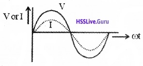
Where I0 = Vo/R is the peak value of current. Comparing eq(1) and eq(2), we can understand that the current and voltage are in same phase.
Graphical variation of current and voltage:
R.M.S value (or Virtual value, effective value) of current and voltage:
The mean value of emf and current for one cycle is zero. Hence to measure ac, the root mean square (rms) values are considered.
![]()
The r.m.s value or virtual value of an AC is the square root of the mean of the squares of the instantaneous value of current taken over a complete cycle.
Irms = \(\frac{I_{0}}{\sqrt{2}}\) and Vrms = \(\frac{V_{0}}{\sqrt{2}}\)
where I0 – maximum current, V0 – maximum voltage, (r.m.s.- root mean square).
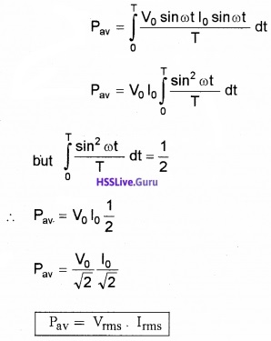
Power dissipated in the resistor:
The average power consumed in one complete cycle,
![]()
Substituting current and voltage, We get
Representation Of Ac Current And Voltage By Rotating Vectors – Phasors
To represent the phase relation between current and voltage, phasors are used. Aphasoris a vector which rotates about the origin with an angular speed ω. The vertical components of phasors of V and I represent instantaneous value of V and I at a time t (see figure). The length of phasors give maximum amplitudes of V and I.
Phasor diagram of v and i for the circuit containing resistor only
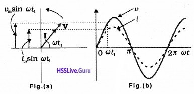
The figure(a) represent the voltage and current phasors and their relationship at time t1. Fig (b) shows the graphical variation of V and I.
![]()
Ac Voltage Applied To An Inductor
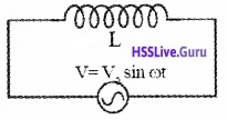
Consider a circuit containing an inductor of inductance ‘L’ connected to an alternating voltage.
Let the applied voltage be
V = Vo sinωt _____(1)
Due to the flow of alternating current through coil, an emf, \(\frac{d I}{d t}\) is produced in the coil. This induced emf is equal and opposite to the applied emf (in the case of ideal inductor)
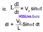
Integrating, we get
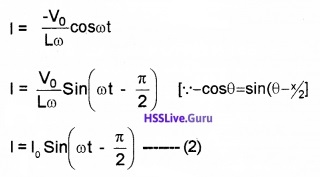
Where Io = \(\frac{V_{0}}{L \omega}\),
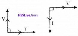
The term Lω is called inductive reactance. Comparing eq(1) and eq(2), we can understand that, the current lags behind the voltage by an angle 90°.
Graphical variation of current and voltage:
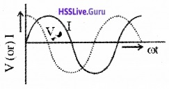
Phasor diagram:
Inductive reactance XL:
The resistance offered by an inductor to a.c. flow is called inductive reactance.
Inductive reactance
![]()
Power Consumed by an Inductor Carrying AC:
The instantaneous value of voltage and current in a pure inductor is
V = Vo sinωt
I = Io cosωt
The average power consumed per cycle.
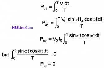
The above expression indicates that the average power or net energy consumed by an inductor carrying ac for a full cycle is zero.
![]()
Ac Voltage Applied To A Capacitor
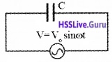
Consider a circuit containing a capacitor of capacitance ‘C’ connected to alternating voltage.
Let the applied voltage be V = Vo sinωt _____(1)
The instantaneous current through capacitor

Substituting eq.(1) in eq.(2), we get

\(\frac{1}{\mathrm{C} \omega}\) is called capacitative reactance
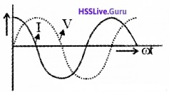
Comparing eq(1) and eq(3), we can understand that, the current leads the voltage by an angle 90°
Graphical variation of current and voltage:
Phaser diagram:

Capacitative Reactance Xc:
The resistance offered by a capacitor to ac flow is called Capacitative reactance
Capacitative reactance

1. Power consumed by a capacitor carrying current:
The instantaneous value of voltage and current in a pure inductor is
V = Vo sinωt
I = Io cosωt
The average power consumed per cycle.

The above expression indicates that the average power or net energy consumed by a capacitor carrying ac for a full cycle is zero.
![]()
Ac Voltage Applied To A Series Lcr Circuit
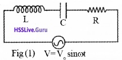
Consider a circuit containing an inductance L, resistance R and capacitance C connected in series. An alternating voltage V = Vo sinωt is applied to the circuit.
Phasor Diagram:

Let VR be the voltage across R. This voltage is represented by a vector OA (since I and VR are in same direction). Let VL be the voltage across L. This voltage is represented by a vector OB (since the voltage VL leads the current by angle 90°).
Similarly, let Vc be the voltage across C. This voltage is represented by a vector OC (since the voltage Vc lags the current by angle 90°).
The phase difference between VL and Vc is Φ(ie. they are in opposite directions). So the magnitude of net voltage across the reactance is (VL – Vc). This is represented by a vector OD in phasor diagram.
The final voltage in the circuit is the vector sum of VR and (VL – Vc). The final voltage is represented by diagonal OE.
1. Impedances of LCR circuit:
From the right angled triangle OAE,
Final voltage, V = \(\sqrt{\mathrm{V}_{\mathrm{R}}^{2}+\left(\mathrm{V}_{\mathrm{L}}-\mathrm{V}_{\mathrm{c}}\right)^{2}}\)
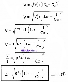
Where Z is called impedance of LCR circuit
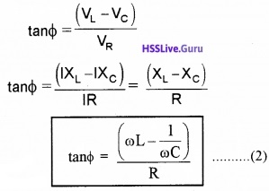
Phase Difference: Let Φ be the phase difference between final voltage V and current I
From fig (2), we can write
![]()
Expression for current:
The eq(2) shows that there is a phase difference between current and voltage. The instantaneous current lags the voltage by an angle (Φ).
If V = Vo sinωt is the applied voltage, the current at any instant can be written as
I = Io sin(ωt – Φ) _____(3)
Where Io is the peak value of current. It’s value can be written as
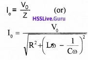
2. Analytical solution:
If we apply V = Vmsinωt to an LCR circuit, we can write
VL + VR + VC = Vm sinωt

Substituting these values in eq.(1), we get

The above equation (2) is like the equation for a forced, damped oscillator. Hence we can take the solution of above equation as
q = qm sin(ωt + θ)
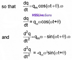
Substituting these values in eq.(2) we get
Multiplying and dividing by Z = \(\sqrt{R^{2}+\left(X_{0}-X_{L}\right)^{2}}\), we have

![]()
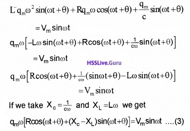
Substituting these values in eq.(4), we get
qmωz[cosΦcos(ωt + θ) + sinΦsin(ωt + θ)] = Vmsinωt
qmωz cos(ωt + θ – Φ) = Vm sinωt ______(5)
(∴ cos(A – B) = cosA cosB + sinA sinB)
Comparing the two sides of the eq.(5) we get
Vm = qmωz = imz
where im = qmω
and cos(ωt + θ – Φ) = sinωt
sin (ωt + θ – Φ + π/2) = sinωt (∵ sin(θ + π/2) = cosθ)
ωt + θ – Φ + π/2 = ωt
(θ – Φ) = -π/2
Therefore, the current in the circuit is
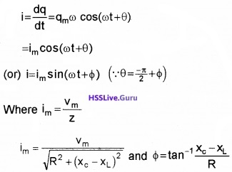
Thus, the analytical solution for the amplitude and phase of the current in the circuit agrees with that obtained by the technique of phasors.
3. Resonance:
When ωL = \(\frac{1}{\omega C}\), the impedance of the LCR circuit becomes minimum. Hence current becomes maximum. This phenomena is called resonance.
The frequency of the applied signal at which the impedance of LCR circuit is minimum and current becomes maximum is called resonance frequency.
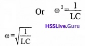
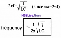
Expression for resonance frequency
Resonance occurs at ωL = \(\frac{1}{\omega C}\)
![]()
Impedance at resonance: Resonance occurs at ωL = \(\frac{1}{\omega C}\). Substituting this condition in eq(1), in section 7.6, we get
Impedance, Z = R
Current at resonance:
substituting ωL = \(\frac{1}{\omega C}\) in eq(2) in section 7.6 we get,
TanΦ = 0, or Φ = 0
Substituting this value in eq(3) in section 7.6, we get
current I= Io sin ωt
Where Io = Vo/R
Graphical variation of current with ω in LCR circuit:

Variation of current through LCR circuit with angular frequency co for two cases (1) R= 100Ω and (2) R=200Ω, is shown in the graph
Note: It is important to note that resonance phenomenon is exhibited by a circuit only if both L and C are present in the circuit. Only then the voltages across L and C cancel each other (both being out of phase).
The current amplitude ( Vm/R) is the total source voltage appearing across R. This means that we cannot have resonance in a RL or RC circuit.
4. Sharpness of resonance:
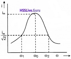
The figure shows the variation of current i with © in a LCR circuit.
Bandwidth: At ω0, the current in the LCR circuit is maximum. Suppose we choose a value of ω for which the current amplitude is \(\frac{1}{\sqrt{2}}\) times its maximum value.
We can see that there are two values of ω(ω1 and ω2) and forwhich current is \(\frac{i_{m}}{\sqrt{2}}\).
The difference ω2 – ω1 is called bandwidth.
If we take ω1 = ω0 – ∆ω and ω2 = ω0 + ∆ω
We get bandwidth, ω2 – ω1 = 2∆ω.
![]()
Expression for bandwidth and sharpness of resonance:
We know that the current in the LCR circuit
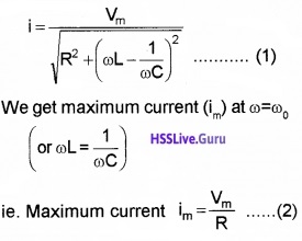
We know that the current in the LCR circuit becomes \(\frac{i_{m}}{\sqrt{2}}\) at ω2 = ω0 + ∆ω. Substituting this m in eq(1), we get
But ω2 = ω0 + ∆ω, substituting this above equation.


![]()
Sharpness of resonance: The quantity \(\left(\frac{\omega_{0}}{2 \Delta \omega}\right)\) is
called sharpness of resonance.
From eq.(4),weget

When bandwidth increases, the sharpness of resonance decreases, ie. the tuning of the circuit will not be good.
Quality Factor (Q): The ratio \(\frac{\omega_{0} L}{R}\) is called the quality factor. When R is low or L is large, the quality factor becomes large. Lange quality factor means that the circuit is more selective.
Power in AC circuit: The power factor
Power in AC circuit with LC and R: In ac circuit the Voltage vary continuously.
∴ The average power in the circuit for one full cycle of period,

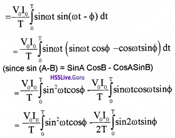
(since sin 2A = 2sinA CosA)
The mean value of sin2ωt over a complete cycle is 1/2 and the mean value of sin2ωt over a complete cycle is zero.

True power = Apparent power × power factor
The term Pav called true power. Vrms × Irms is called the apparent power and cosΦ is called power factor.
powerfactor = \(\frac{\text { True power }}{\text { apparent power }}\)
Power factor is defined as the ratio of true power to apparent power.
![]()
Case – 1 (In purely resistive circuit)
In this case, current and voltage are in same phase. Hence Φ = 0
∴ Pav = Vrms IrmsCosO
True power, Pav = Vrms Irms
Case – 2 (In a purely inductive and purely capacitative circuit (no resistance)). In this case, the angle between voltage and current is 90°.
∴ Pav = Vrms IrmsCos 90
True power, Pav = 0
Which means that, the power consumed by the circuit is zero. The current in such a circuit (purely inductive and purely capacitive) doesn’t do any work. A current that does not do any work is called wattles or idle current.
Lc Oscillations

A capacitor can store electrical energy. An inductor can store magnetic energy. When a charged capacitor is connected to an inductor, the electrical energy( of capacitor) transfers to magnetic energy (of inductor) and vise versa. Thus energy oscillates back and forth between capacitor and inductor. This is called L. C. Oscillations.
Expression for frequency:
Applying Kirchoff’s second rule, we get

![]()
Transformers
Principle: It works on the principle of mutual induction.
Construction:

A transformer consists of two insulated coils wound over a core. The coil, to which energy is given is called primary and that from which energy is taken is called secondary.
Working and mathematical expression :
Let V1 N1 be the voltage and number of turns in the primary. Similarly, let V2, N2 be voltage and number of turns in the secondary.
When AC is passed, a change in magnetic flux is produced in the primary. This magnetic flux passes through secondary coil.
If Φ1 and Φ2 are the magnetic flux of primary and secondary, we can write Φ1 α N1 and Φ2 α N2.
Dividing Φ1 and Φ2
\(\frac{\phi_{1}}{\phi_{2}}=\frac{N_{1}}{N_{2}}\)
[since Φ is proportional to number of turns] or \(\phi_{1}=\frac{\mathrm{N}_{1}}{\mathrm{N}_{2}} \phi_{2}\)
Taking differentiation on both sides we get

Step up Transformer:
If the output voltage is greater than input voltage, the transformer is called step up transformer. In a step up transformer N2 > N1 and V2 > V1.
Step down transformer:
If the output voltage is less than the input voltage, then the transformer is called step down transformer. In a step down transformer N2 < N1 and V2 < V1.
Efficiency of a transformer:
The efficiency of a transformer is defined as the ratio of output power to input power.

For an ideal transformer, efficiency = 1
i.e, V1I1 = V2I2
![]()
1. Power losses in a transformer
(i) Joule loss or Copper loss:
When current passes through a coil heat is produced. This energy loss is called Joule loss. It can be minimized by using thick wires.
(ii) Eddy current loss: This can be minimized by using laminated cores. Laminated core increases the resistance of the coil. Thus eddy current decreases.
(iii) Hysteresis loss: When the iron core undergoes cycles of magnetization, energy is lost. This loss is called hysteresis loss. This is minimized by using soft iron core.
(iv) Magnetic flux loss:
The total flux linked with the coil may not pass through secondary coil. This loss is called magnetic flux loss. This loss can be minimized by closely winding the wires.