Plus Two Physics Notes Chapter 12 Atoms

Students can Download Chapter 12 Atoms Notes, Plus Two Physics Notes helps you to revise the complete Kerala State Syllabus and score more marks in your examinations.

Kerala Plus Two Physics Notes Chapter 12 Atoms

Introduction
What is the arrangement of +ve charge and the electrons inside the atom? In other words, what is the structure of an atom?

Alpha-particle Scattering And Rutherford’s Nuclear Model Of Atom
Rutherford’s scattering experiment:
Plus Two Physics Notes Chapter 12 Atoms - 1

Experimental arrangement:
α particles are incident on a gold foil (very small thickness) through a lead collimator. They are scattered at different angles. The scattered particles are counted by a particle detector.

Observations:
Most of the alpha particles are scattered by small angles. A few alpha particles are scattered at an angle greater than 90°.

Plus Two Physics Notes Chapter 12 Atoms

Conclusions

  1. Major portion of the atom is empty space.
  2. All the positive charges of the atom are concentrated in a small portion of the atom.
  3. The whole mass of the atom is concentrated in a small portion of the atom.

Rutherford’s model of atom

  1. The massive part of the atom (nucleus) is concentrated at the centre of the atom.
  2. The nucleus contains all the positive charges of the atom.
  3. The size of the nucleus is the order of 10-15m.
  4. Electrons move around the nucleus in circular orbits.
  5. The electrostatic force of attraction (between proton and electron) provides centripetal force.

1. Alpha-particle trajectory and Impact parameter:
The impact parameter is the perpendicular distance of the initial velocity vector of the a particle from the centre of the nucleus.
Plus Two Physics Notes Chapter 12 Atoms - 2
It is seen that an α particle close to the nucleus (small impact parameter) suffers large scattering. In case of head-on collision, the impact parameter is minimum and the α particle rebounds back. For a large impact parameter, the α particle goes nearly undeviated and has a small deflection.

2. Electron orbits (Rutherford model of atom):
In Rutherford atom model, electrons are revolving around the positively charged nucleus. The electro-static force of attraction between the positive charge and negative charge provide centripetal force required for rotation.
For a dynamically stable orbit,
Centripetal force = Electrostatic force of attraction
Fc = Fe
Plus Two Physics Notes Chapter 12 Atoms - 3
Thus the relation between the orbit radius and the electrons velocity,
Plus Two Physics Notes Chapter 12 Atoms - 4
Total energy of electron of Hydrogen atom (Rutherford model atom):
From eq. (1), we get
Plus Two Physics Notes Chapter 12 Atoms - 5

Plus Two Physics Notes Chapter 12 Atoms
∴ Kinetic energy of electron
KE = \(\frac{1}{2}\)mv2 ……….(3)
Substituting eq.(2) in eq. (3) we get
KE = \(\frac{e^{2}}{8 \pi \varepsilon_{0} r}\) …………(4)
The electrostatic potential energy of hydrogen atom
\(\frac{e^{2}}{8 \pi \varepsilon_{0} r}\)
u = \(\frac{-e^{2}}{4 \pi \varepsilon_{0} r}\) ………..(5)
∴ The total energy E of the electron in a hydrogen atom
E = K.E + Potential energy (U)
Plus Two Physics Notes Chapter 12 Atoms - 6
The total energy of the electron is negative. This implies that the electron is bound to the nucleus.
If E is positive, the electron will escape from the nucleus.

Atomic Spectra
There are two types of spectra

  1. Emission spectra
  2. Absorption spectra

1. Emission spectra:
When an atomic gas or vapor is excited, the emitted radiation has a spectrum which contains certain wavelength only. A spectrum of this kind is termed as emission line spectrum. It consists of bright lines on a dark background.

Absorption spectra:
When white light passed through a gas, the transmitted light has spectrum contain certain wavelength only. A spectrum of this kind is termed as absorption line spectrum. It consists of dark lines on a bright background.

1. Spectral series:
Plus Two Physics Notes Chapter 12 Atoms - 7
The frequencies of the light emitted by a particular element exhibit some regular pattern. Hydrogen is the simplest atom and therefore, has the simplest spectrum, the spacing between lines of the hydrogen spectrum decreases in a regular way. Each of these sets is called a spectral series.

The first such series was observed by a Johann Jakob Balmer in the visible region of the hydrogen spectrum. This series is called Balmer series. Balmer found a simple empirical formula for the observed wavelengths.
Plus Two Physics Notes Chapter 12 Atoms - 8
where λ is the wavelength, R is a constant called the Rydberg constant, and n may have integral values 3, 4, 5, etc. The value of R is 1.097 × 10⁷m-1. This equation is also called Balmer formula.

Other series of spectra for hydrogen were discovered. These are known, as Lyman, Paschen, Brackett, and Pfund series. These are represented by the formulae:
Lyman series:
Plus Two Physics Notes Chapter 12 Atoms - 9

Plus Two Physics Notes Chapter 12 Atoms
Balmer series:
Plus Two Physics Notes Chapter 12 Atoms - 10
Paschen series:
This series is in the infrared region. For this series the electron must jump from higher orbit to the third orbit.
Plus Two Physics Notes Chapter 12 Atoms - 11
Bracket series:
This series is the infrared region, for this the electron must jump from higher energy level to fourth orbit.
Plus Two Physics Notes Chapter 12 Atoms - 12
P-fund series:
This series is in the infrared region.
Plus Two Physics Notes Chapter 12 Atoms - 13

Bohr Model Of Hydrogen Atom
Limitations of Rutherford model:
1. Circular motion is an accelerated motion, an accelerated charge emit radiations. So that electron should emit radiation. Due to this emission of radiation, the energy of the electron decreases. Thus the atom becomes unstable.

2. There is no restriction for the radius of the orbit. So that electron can emit radiations of any frequency.

Bohr postulates:
Bohr combined classical and early quantum concepts and gave his theory in the form of three postulates.

  • Electrons revolve round the positively charged nucleus in circular orbits.
  • The electron which remains in a privileged path cannot radiate its energy.
  • The orbital angular momentum of the electron is an integral multiple of h/π.
  • Emission or Absorption of energy takes place when an electron jumps from one orbit to another.

Radius of the hydrogen atom:
Consider an electron of charge ‘e’ and mass m revolving round the positively charged nucleus in circular orbit of radius ‘r’. The force of attraction between the nucleus and the electron is
Plus Two Physics Notes Chapter 12 Atoms - 14
This force provides the centripetal force for the orbiting electron
Plus Two Physics Notes Chapter 12 Atoms - 15

Plus Two Physics Notes Chapter 12 Atoms
According to Bohr’s second postulate, we can write
Angular momentum, mvr \(=\frac{n h}{2 \pi}\).
ie. v = \(\frac{n h}{2 \pi m r}\) _____(4)
Substituting this value of ‘v’ in equation (2), we get
Plus Two Physics Notes Chapter 12 Atoms - 16
Energy of the hydrogen atom:
The K.E. of revolving electron is
K.E\(=\frac{1}{2}\) mv2 ______(6)
Substituting the value of equation (3) in eq.(6), we get
K.E = \(\frac{1}{2} \frac{e^{2}}{4 \pi \varepsilon_{0} r}\) ______(7)
The potential energy of the electron,
P.E = \(\frac{-e^{2}}{4 \pi \varepsilon_{0} r}\) _______(8)
ie. The Total energy of the hydrogen atom is,
T.E = Ke + PE
Plus Two Physics Notes Chapter 12 Atoms - 17
Substituting the value of equation (5) in equation (9) we get
Plus Two Physics Notes Chapter 12 Atoms - 18

Plus Two Physics Notes Chapter 12 Atoms

1. Energy levels
Ground state (E1):
Ground state is the lowest energy state, in which the electron revolving in the orbit of smallest radius.
For ground state n = 1
∴ Energy of hydrogen atom E1 = \(\frac{-13.6}{n^{2}}\) = -13.6 ev.

Excited State (E2):
When hydrogen atom receives energy, the electrons may raise to higher energy levels. Then atom is said to be in excited state.

First Excited state:
For first excited state n = 2
∴ Energy of first excited state E2 = \(\frac{-13.6}{2^{2}}\) = -3.04ev
Similarly energy of second excited state
E3 = \(\frac{-13.6}{3^{2}}\) = -1.51ev

Energy difference between E1 and E2 of H atom:
The energy required to exist an electron in hydrogen atom to its first existed state.
∆E = E2 – E1 = 3.4 – 13.6 = 10.2eV.

Ionization energy:
Ionization energy is the minimum energy required to free the electron from the ground state of atom. (ie. n = 1 to n = ∞)
The ionization of energy of hydrogen atom = 13.6 ev

2. Energy level diagram of hydrogen atom:
Plus Two Physics Notes Chapter 12 Atoms - 19
Note:
An electron can have any total energy above E = 0ev. In such situations electron is free. Thus there is a continuum of energy states above E = 0ev.

The Line Spectra Of The Hydrogen Atom
According to the third postulate of Bohr’s model, when an atom makes a transition from higher energy state (ni) to lower energy state (nf), photon of energy hvif is emitted.
ie. hνif = Eni – Enf

Plus Two Physics Notes Chapter 12 Atoms

De Broglie’s Explanation Of Bohr’s Second Postulate Of Quantization
Louis de Broglie argued that the electron in its circular orbit, behalf as a particle wave. Particle waves can produce standing waves under resonant conditions.
The condition to get standing wave,
2πrn = nλ
n = 1, 2, 3……..
The quantized electron orbits and energy states are due to the wave nature of the electron.

DeBroglie’s Proof for Bohr’s second postulate:
According to De Broglie, the electron in a circuit orbit is a particle wave. The particle wave can produce standing waves under resonant conditions. The condition for resonance for an electron moving in nth circular orbit of radius rn,
2πrn = nλ______(1)
n = 1, 2, 3………
If the speed of electron is much less than the speed of light, wave length
Plus Two Physics Notes Chapter 12 Atoms - 20

Plus Two Physics Notes Chapter 12 Atoms
Note:
The quantized electron orbits and energy states are due to the wave nature of the electron.

Limitations of Bohr atom model:

  1. The Bohr model is applicable to hydrogenic atoms. It cannot be extended to many electron atoms such as helium
  2. The model is unable to explain the relative intensities of the frequencies in the spectrum.
  3. Bohr model could not explain fine structure of spectral lines.
  4. Bohr theory could not give a satisfactory explanation for circular orbit.

Plus Two Physics Notes Chapter 11 Dual Nature of Radiation and Matter

Students can Download Chapter 11 Dual Nature of Radiation and Matter Notes, Plus Two Physics Notes helps you to revise the complete Kerala State Syllabus and score more marks in your examinations.

Kerala Plus Two Physics Notes Chapter 11 Dual Nature of Radiation and Matter

Introduction
The discovery of cathode rays by Rontgen and discovery of electrons by JJ Thomson were important milestones in the study of atomic structure.

Electron Emission
We know that metals have free electrons. The free electrons cannot normally escape out of the metal surface. If an electron attempts to come out of the metal, the metal surface acquires a positive charge. This positive surface held electrons inside the metal surface.

Plus Two Physics Notes Chapter 11 Dual Nature of Radiation and Matter

Work function:
When we give energy to electron in a metal, it can come out of metal. This minimum energy required by an electron to escape from the metal surface is called the work function of the metal. It is generally denoted by Φ0(hν0) and measured in eV (electron volt).

Electron volt:
One electron volt is the energy gained by an electron when it has been accelerated by a potential difference of 1 volt
1 eV = 1.602 × 10⁻¹⁹J.
This unit of energy is commonly used in atomic and nuclear physics.

Different types of electron emission:
The minimum energy required for the electron emission from the metal surface can be supplied by any one of the following methods.

(i) Thermionic emission:
Electrons can come out of metal surface, if heat energy is given to metal.

(ii) Field emission:
By applying a very strong electric field (of the order of 108 Vm-1) to a metal, electrons can be pulled out of the metal.

(iii) Photoelectric emission:
When light (of suitable frequency) incident on a metal surface, electrons are emitted from the metal surface. These electrons are called photoelectrons. This phenomena is called photo electric effect.

Plus Two Physics Notes Chapter 11 Dual Nature of Radiation and Matter

Photoelectric Effect
1. Hertz’s observations:
The phenomenon of photoelectric emission was discovered by Heinrich Hertz in 1887, Heinrich Hertz observed that when light falls on a metal surface, electrons escape from the metal surface.

2. Hallwachs’ and Lenard’s observations:
Wilhelm Hallwachs and Philipp Lenard investigated the phenomenon of photoelectric emission in detail. The experimental set up consist of two metal plates (cathode and anode) inside a evacuated glass tube as shown in figure.

They observed that current flpws in the circuit when emitter plate (C) was illuminated by UV radiation. It means that when light incident on a metal plate electrons are emitted. These electrons move towards the anode and results in current flow.
Plus Two Physics Notes Chapter 11 Dual Nature of Radiation and Matter - 1
They also observed that, when a negatively charged zinc plate is illuminated by UV light, it becomes chargeless. He also observed that uncharged Zn plate becomes positively charged when it is illuminated with UV light.

From these observations they concluded that the particles emitted carry negative charge.

Threshold frequency:
The minimum frequency (ν0) required to produce photo electric effect is called the threshold frequency. It depends on the nature of material.

Experimental Study Of Photoelectric Effect
The experimental setup:
Plus Two Physics Notes Chapter 11 Dual Nature of Radiation and Matter - 2

Plus Two Physics Notes Chapter 11 Dual Nature of Radiation and Matter
The experimental arrangement consists of two zinc plates enclosed in a quartz bulb. The plates are connected to a battery through a micro ammeter. When ultraviolet light is incident on the cathode plate, the micrometer indicates a current in the circuit.

When the anode is made negative (with respect to cathode) the current decreases and at a certain voltage (V0), current is completely stopped. This voltage V0 is called stopping potential. At this stage,
\(\frac{1}{2}\) mVmax2 = eV0
where vmax is the maximum kinetic energy of photo electrons.

1. Effect of intensity of light on photocurrent Experiment:
In this experiment the collector A is maintained at a positive potential. The frequency of the incident radiation and the accelerating potential are kept at fixed.

Then change the intensity of light and measure photoelectric current in each time. Draw a graph between photo current and intensity of light. We get a graph as shown in figure.

Observations:
This graph shows that photocurrent increases linearly with intensity of incident light.
Plus Two Physics Notes Chapter 11 Dual Nature of Radiation and Matter - 3

Conclusion:
The photocurrent is directly proportional to the number of photoelectrons emitted per second. This implies that the number off Photoelectrons emitted per second is directly proportional to the intensity of incident radiation.

Plus Two Physics Notes Chapter 11 Dual Nature of Radiation and Matter

2. Effect of potential on photoelectric current Experiment:
Keep the plate A at positive accelerating potential. Then illuminate the plate C with light (of fixed frequency v and fixed intensity I1). Then vary the positive potential of plate A gradually and measure the resulting photocurrent each time.

When the photo current reaches maximum, the polarity of plates are reversed and thus apply a negative potential (retarding potential) to plate A.

Again photocurrent is measured by varying the retarding potential till photocurrent reaches zero. The experiment is repeated for higher intensity I2 and I3 keeping the frequency fixed.

Observations:
As accelerating potential increases photo current increases. At a particular anode potential photocurrent reaches maximum. Further increase in accelerating potential does not increase photo current.

When we apply negative potential to A, photo electrons get retarded and hence photocurrent decreases. At particular retarding potential photocurrent becomes zero. This potential is called cut off or stopping potential.

The graph of anode potential with photo current:
Plus Two Physics Notes Chapter 11 Dual Nature of Radiation and Matter - 4
The saturation current is found to be large at higher intensity (because photo current is directly proportional to intensity). But stopping potential is same for different intensity at fixed frequency, (ie. for a given frequency of incident radiation stopping potential is independent of its intensity).
Plus Two Physics Notes Chapter 11 Dual Nature of Radiation and Matter - 5

Plus Two Physics Notes Chapter 11 Dual Nature of Radiation and Matter

Note:
a. The maximum value of photo current is called saturation current (Isat).

b. The retarding anode potential at which photo current reaches zero is called stopping potential (V0).

When retarding potential is applied, only most energetic electrons can reach collector plate A. At stopping potential no electrons reach plate A, ie stopping potential is sufficient to repel the electron with maximum kinetic energy
Plus Two Physics Notes Chapter 11 Dual Nature of Radiation and Matter - 6

c. The stopping potential or maximum value of KE depends only on frequency of incident light, not on its intensity. Hence stopping potential is same for different intensity at constant frequency.

d. At zero anode potential, photocurrent is not zero, ie photo electric effect takes place even if anode potential is not applied.

3. Effect of frequency of incident radiation on stopping potential:
Experiment:
In this experiment, we adjust the intensity of light at various frequencies (say ν1, ν2 and ν3 such that ν1 < ν2 < ν3) and study the variation of photocurrent with collector plate potential.

Observations:
Plus Two Physics Notes Chapter 11 Dual Nature of Radiation and Matter - 7
For frequencies ν1, ν2 and ν31 < ν2 < ν3) τηε stopping potential are found to be V03 > V02 > V01. It means that stopping potential varies linearly with incident frequency fora given photosensitive material.

The graph of stopping potential with frequency:
Plus Two Physics Notes Chapter 11 Dual Nature of Radiation and Matter - 8

Plus Two Physics Notes Chapter 11 Dual Nature of Radiation and Matter
The graph shows that

  • The stopping potential V0 varies linearly with the frequency of incident radiation for a given photosensitive material,
  • There exists a certain minimum cutoff frequency ν0 for which the stopping potential is zero.

These observations have two implications:

  • The maximum kinetic energy of the photoelectrons varies linearly with the frequency of incident radiation, but is independent of its intensity.
  • Fora frequency ν of incident radiation, lower than the cutoff frequency ν0, no photoelectric emission is possible even if the intensity is large.
  • For a frequency ν0, no photoelectric emission is possible even if the intensity is large. This minimum, cutoff frequency ν0, is called the threshold frequency. It is different for different metals.

Summary of the experimental features and observations:
Laws of photoelectric emission:

  1. For a given frequency of radiation, number of photoelectrons emitted is proportional to the intensity of incident radiation.
  2. The kinetic energy of photoelectrons depends on the frequency of incident light but it is independent of the light intensity.
  3. Photoelectric effect does not occur if the frequency is below a certain value. The minimum frequency (ν0) required to produce photo electric effect is called the threshold frequency.
  4. Photoelectric effect is an instantaneous phenomenon.

Photoelectric Effect And Wave Theory Of Light
Wage theory of light is not used to explain photo electric effect. Why?
Reasons
1. According to wave theory, when intensity of incident wave increases, the KE of electron must be increased. This is pgainst the experimental observation of photoelectric effect.

2. According to wave theory, absorption of energy by electron takes place continuously. A large number of electrons absorb energy from the wave at a time.

Hence energy received by a single electron will be small. Hence it takes hours to eject an electron from a metal surface. This delay in photoemission is against the experimental observation.

Plus Two Physics Notes Chapter 11 Dual Nature of Radiation and Matter

Einstein’s Photoelectric Equation
Energy quantum of radiation:
Einstein explained photoelectric effect based on quantum theory. According to quantum theory, light contain photons having energy hν, when a photon of energy hr incidents on a metal surface, electrons are liberated.

A small portion of the photon energy is used for work function (Φ) and remaining energy is appeared as K.E of the electron.

By law of conservation of energy, we can write,
Photon energy = work function + K.E of electrons
hν = Φ + \(\frac{1}{2}\) mv2
\(\frac{1}{2}\)mv2 = hν – Φ______(1)
If threshold frequency ν0 is incident, we can take K.E = 0
So eq(1) can be written as
0 = hν0 – Φ
i.e. work function Φ = hν0______(2)
Substituting eq(2) in eq(1) we get
\(\frac{1}{2}\)mv2 = hν – hν0
\(\frac{1}{2}\)mv2 = h(ν – ν0)______(3)
This is Einstein’s Photoelectric equation.
But we know ν = c/λ and ν0 = c/λ0
Substituting these values in eq(3) we get,
Plus Two Physics Notes Chapter 11 Dual Nature of Radiation and Matter - 9

Plus Two Physics Notes Chapter 11 Dual Nature of Radiation and Matter
Discussion (explanation of photo electric effect on the basis of Einstein’s photo electric equation):
1. If the intensity of the incident light increases, more number of photons interact with electrons and more number of electrons are emitted. Thus the electric current increases with the intensity of the incident light.

2. For a given metal, Φ0(hν0) is constant. Hence from 1/2mv2 = hν – hν0, we can understand that KE depends on ‘V’ (incident frequency).

3. From this equation 1/2mv2 = hν – hν0. we can understand that photoemission is not possible, if ν < ν0.

4. According to quantum theory, a photon interacts only with a single electron (no sharing of energy takes place) so that there is no time delay in photoelectric emission.

Particle Nature Of Light: The Photon:
The photon picture of electromagnetic radiation is as follows:

  1. In interaction of radiation with matter, radiation behaves as if it is made up of particles called photons.
  2. Each photon has energy E and momentum ρ.
  3. Photon energy is independent of intensity of radiation.
  4. Photons are electrically neutral and are not deflected by electric and magnetic fields.
  5. In a photon-particle collision the total energy and total momentum are conserved.

Plus Two Physics Notes Chapter 11 Dual Nature of Radiation and Matter

Wave Nature Of Matter
In 1924, the French physicist Louis Victorde Broglie put forward the hypothesis, that moving particles of matter should display wavelike properties under suitable conditions.

The waves associated with material particles are known as matter waves or de-Broglie’s waves. de-Broglie wave is seen with microscopic particles like proton, electron, and neutron, etc. The wave length of matter waves is called de-Broglie wave length.
De-Broglie wave length,
Plus Two Physics Notes Chapter 11 Dual Nature of Radiation and Matter - 10
h – Plank’s constant, m – mass of the particle, v – velocity of the particle.

1. Wavelength of matter waves:
The energy of photon E = hν _____(1)
If photon is considered as a particle of mass ‘m’, the energy of photon can be written as
E = mc2 _____(2)
From eq(1) and eq (2) we get
hν = mc2
m = \(\frac{\mathrm{hv}}{\mathrm{c}^{2}}\) ________(3)
Momentum of the electron can be written as
P = mass × velocity ______(4)
Substituting eq (3) in eq(4) ,we get
Plus Two Physics Notes Chapter 11 Dual Nature of Radiation and Matter - 11
Plus Two Physics Notes Chapter 11 Dual Nature of Radiation and Matter - 12

The wave length of electron wave:
If electron of mass ‘m’ and charge ‘e’ is accelerated through a p.d of V volt, the de-Broglie wavelength can be written as
Plus Two Physics Notes Chapter 11 Dual Nature of Radiation and Matter - 13

Plus Two Physics Notes Chapter 11 Dual Nature of Radiation and Matter

2. Uncertainty Principle:
According to the principle, it is not possible to measure both the position and momentum of an electron (or any other particle) at the same time exactly.

If (∆x) is the uncertainty in position and (∆p) is the uncertainties in momemtum, the product uncertainties is given by
∆x.∆p =\(\frac{h}{2 \pi}\)

The above equation allows the possibility that if ∆x is zero; then ∆p must be infinite in order that the product is nonzero. Similarly, if ∆p is zero, ∆x must be infinite.

The wave packet description of an electron:
Plus Two Physics Notes Chapter 11 Dual Nature of Radiation and Matter - 14
The above wave packet description of matter wave corresponds to an uncertainty in position (∆x) and an uncertainty in momentum (∆p).

Wave packet description for ∆p = 0:
Plus Two Physics Notes Chapter 11 Dual Nature of Radiation and Matter - 15
The above wavepacket description of matter wave corresponds to a definite momentum of an electron extends all over space. In this case, ∆p = 0 and
∆x → ∞

Plus Two Physics Notes Chapter 11 Dual Nature of Radiation and Matter

Davisson Germer Experiment
Plus Two Physics Notes Chapter 11 Dual Nature of Radiation and Matter - 16
Aim: To confirm the wave nature of electron.
Experimental setup:
The Davisson and Germer Experiment consists of filament ‘F’, which is connected to a low tension battery. The Anode Plate (A) is used to accelerate the beam of electrons. A high voltage is applied in between A and C. ’N’ is a nickel crystal. D is an electron detector. It can be rotated on a circular scale. Detector produces current according to the intensity of incident beam.

Working:
The electron beam is produced by passing current through filament F. The electron beam is accelerated by applying a voltage in between A (anode) and C. The accelerated electron beam is made to fall on the nickel crystal.

The nickel crystal scatters the electron beam to different angles. The crystal is fixed at an angle of Φ = 50° to the incident beam.

The detector current for different values of the accelerating potential ‘V’ is measured. A graph between detector current and voltage (accelerating) is plotted. The shape of the graph is shown in figure.

Analysis of graph:
Plus Two Physics Notes Chapter 11 Dual Nature of Radiation and Matter - 17
The graph shows that the detector current increases with accelerating voltage and attains maximum value at 54V and then decreases. The maximum value of current at 54 V is due to the constructive interference of scattered waves from nickel crystal (from different planes of crystal). Thus wave nature of electron is established.

Experimental wavelength of electron:
The wave length of the electron can be found from the formula
2d sinθ = nλ ______(1)
From the figure, we get
θ + Φ + θ = 180°
2θ = 180 – Φ, 2θ = 180 – 50°
θ = 65°
for n = 1

Plus Two Physics Notes Chapter 11 Dual Nature of Radiation and Matter
equation (1) becomes
λ = 2dsinθ_____(2)
for Ni crystal, d = 0.91 A°
Substituting this in eq. (2), we get
wavelength λ = 1.65 A°
Theoretical wave length of electron:
The accelerating voltage is 54 V
Energy of electron E = 54 × 1.6 × 1019J
∴ Momentum of electron P = \(\sqrt{2 \mathrm{mE}}\)
Plus Two Physics Notes Chapter 11 Dual Nature of Radiation and Matter - 18
= 39.65 × 10⁻²⁵ Kg ms-1
∴ De-Broglie wavelength λ = \(\frac{h}{P}\)
Plus Two Physics Notes Chapter 11 Dual Nature of Radiation and Matter - 19
Discussion:
The experimentally measured wavelength is found in agreement with de-Broglie wave length. Thus wave nature of electron is confirmed.

Plus Two Physics Notes Chapter 10 Wave Optic

Students can Download Chapter 10 Wave Optic Notes, Plus Two Physics Notes helps you to revise the complete Kerala State Syllabus and score more marks in your examinations.

Kerala Plus Two Physics Notes Chapter 10 Wave Optic

Introduction
In 1678, the Dutch physicist Christian Huygens put forward the wave theory of light. We will discuss in this chapter.

Wavefront:
The wavefront is defined as the locus of all points which have the same phase of vibration. The rays of light are normal to the wavefront. Wavefront can be divided into 3.

  1. Spherical wavefront
  2. Cylindrical wavefront
  3. Plane wavefront.

Plus Two Physics Notes Chapter 10 Wave Optic

1. Spherical Wavefront:
Plus Two Physics Notes Chapter 10 Wave Optic - 1
The wavefront originating from a point source is spherical wavefront.

2. Cylindrical Wavefront:
Plus Two Physics Notes Chapter 10 Wave Optic - 2
If the source is linear, the wavefront is cylindrical.

3. Plane wavefront:
If the source is at infinity, we get plane wavefront.
Plus Two Physics Notes Chapter 10 Wave Optic - 3

Huygen’s Principle
According to Huygen’s principle

  1. Every point in a wavefront acts as a source of secondary wavelets.
  2. The secondary wavelets travel with the same velocity as the original value.
  3. The envelope of all these secondary wavelets gives a new wavefront.

Plus Two Physics Notes Chapter 10 Wave Optic

Refraction And Reflection Of Plane Waves Using Hygens Principle
1. Refraction of a plane wave. (To prove Snell’s law):
AB is the incident wavefront and c1 is the velocity of the wavefront in the first medium. CD is the refracted wavefront and c2 is the velocity of the wavefront in the second medium. AC is a plane separating the two media.
Plus Two Physics Notes Chapter 10 Wave Optic - 4
The time taken for the ray to travel from P to R is
Plus Two Physics Notes Chapter 10 Wave Optic - 5
O is an arbitrary point. Hence AO is a variable. But the time to travel a wavefront from AB to CD is constant. In order to satisfy this condition, the term containing AO in eq.(2) should be zero.
Plus Two Physics Notes Chapter 10 Wave Optic - 6
where 1n2 is the refractive index of the second medium w.r.t. the first. This is the law of refraction.

Plus Two Physics Notes Chapter 10 Wave Optic

2. Reflection of plane wave by a plane surface:
Plus Two Physics Notes Chapter 10 Wave Optic - 7
AB is the incident wavefront and CD is the reflected wavefront, ‘i’ is the angle of incidence and ‘r’ is the angle of reflection. Let c1 be the velocity of light in the medium. Let PO be the incident ray and OQ be the reflected ray.
The time taken for the ray to travel from P to Q is
Plus Two Physics Notes Chapter 10 Wave Optic - 8
O is an arbitrary point. Hence AO is a variable. But the time to travel for a wave front from AB to CD is a constant. So eq.(2) should be independent of AO. i.e., the term containing AO in eq.(2) should be zero. AO
∴ \(\frac{A O}{C_{1}}\)(sin i – sin r) = 0
sin i – sin r= 0
sin i = sin r
i = r
This is the law of reflection.
Behavior of wave frond as they undergo refraction or reflection.

a. Wave frond through the prism:
Plus Two Physics Notes Chapter 10 Wave Optic - 9
Consider a plane wave passing through a thin prism. The speed of light waves is less in glass. Hence the lower portion of the incoming wave frond will get delayed. So outgoing wavefrond will be tilted as shown in the figure.

b. Wave frond through a thin convex lens:
Plus Two Physics Notes Chapter 10 Wave Optic - 10

Plus Two Physics Notes Chapter 10 Wave Optic
Consider a plane wave passing through a thin convex lens. The central part of the incident plane wave travels through the thickest portion of lens.

Hence central part get delayed. As a result the emerging wavefrond has a depression at the centre. Therefore the wave front becomes spherical and converges to a point F.

c. Plane wave incident on a concave mirror:
Plus Two Physics Notes Chapter 10 Wave Optic - 11
A plane wave is incident on a concave mirror and on reflection we have spherical wave converging to the focul point F.

3. The Doppler Effect:
There is an apparent change in the frequency of light when the source or observer moves with respect to one another. This phenomenon is known as Doppler effect in light.

When the source moves away from the observer the wavelength as measured by the source will be larger. The increase in wavelength due to Doppler effect is called as red shift.

When waves are received from a source moving towards the observer, there is an apparent decrease in wavelength, this is referred to as blue shift.

Mathematical expression for Doppler shift:
The Doppler shift can be expressed as
Plus Two Physics Notes Chapter 10 Wave Optic - 12
Vradial is the component of source velocity along the line joining the observer to the source.

Plus Two Physics Notes Chapter 10 Wave Optic

Coherent And Incoherent Addition Of Waves
Super position principle:
According to superposition principle, the resultant displacement produced by a number of waves at a particular point in the medium is the vector sum of the displacements produced by each of the waves.

Coherent sources:
Two sources are said to be coherent, if the phase difference between the displacements produced by each of the waves does not change with time.

Incoherent sources:
Two sources are said to be coherent, if the phase difference between the displacements produced by each of the waves changes with time.

Constructive interference:
Consider two light waves meet together at a point. If we get maximum displacement at the point of meeting, we call it as constructive interference.

Destructive interference:
Consider two lightwaves meet together at a point. If we get minimum displacement at the point of meeting, we call it as destructive interference.

Mathematical condition for Constructive interference and Destructive interference:
Plus Two Physics Notes Chapter 10 Wave Optic - 13
Consider two sources S1 and S2. Let P be point in the region of s1 and s2. The displacement produced by the source s1 at P.
y1 = a cos ωt
Similarly, the displacement produced by the source s2 at P
y2 = a cos (ωt + Φ)
Where Φ is the phase difference between the displacements produced by s1 and s2
The resultant displacement at P,
Y = y1 + y2
= a cos ωt + a cos (ωt + Φ)
= a (cos ωt + cos (ωt + Φ))
Plus Two Physics Notes Chapter 10 Wave Optic - 14

Plus Two Physics Notes Chapter 10 Wave Optic
Therefore total intensity at P,
Plus Two Physics Notes Chapter 10 Wave Optic - 15

Constructive interference:
If we take phase difference Φ = 0, ±2π, ±4π……., we get maximum intensity (4I0) at P. This is the mathematical condition for constructive interference. The condition for constructive interference can be written in the form of path difference between two waves.
Plus Two Physics Notes Chapter 10 Wave Optic - 16
Where n = 0, 1, 2, 3……..

Destructive interference:
If we take phase difference Φ = ±π, ±3π, ±5π………., we get zero intensity at P. This is the mathematical condition for destructive interference. The condition for destructive interference can be written in the form of path difference between two waves.
Plus Two Physics Notes Chapter 10 Wave Optic - 17
Where n = 0, 1, 2, 3……..

Interference Of Light Waves And Youngs Double Slit Experiment
Young’s double-slit experiment:
Plus Two Physics Notes Chapter 10 Wave Optic - 18
The experiment consists of a slit ‘S’. A monochromatic light illuminates this slit. S1 and S2 are two slits in front of the slit ‘S’. A screen is placed at a suitable distance from S1 and S2. Light from S1 and S2 falls on the screen. On the screen interference bands can be seen.

Explanation:
If crests (ortroughs) from S1 and S2 meet at certain points on the screen, the interference of these points will be constructive and we get bright bands on the screen.

At certain points on the screen, crest and trough meet together. Destructive interference takes place at those points. So we get dark bands.

Expression for band width:
Plus Two Physics Notes Chapter 10 Wave Optic - 19
S1 and S2 are two coherent sources having wave length λ. Let ‘d’ be the distance between two coherent sources. A screen is placed at a distance D from sources. ‘O’ is a point on the screen equidistant from S1 and S2.
Hence the path difference, S1O – S2O = 0
So at ‘O’ maximum brightness is obtained.
Let ‘P’ be the position of nth bright band at a distance xn from O. Draw S1A and S2B as shown in figure. From the right angle ∆S1AP
we get, S1P2 = S1A2 + AP2
S1P2 = D2 + (Xn – d/2)2 = D2 + Xn2 – Xnd + \(\frac{d^{4}}{4}\)
Similarly from ∆S2BP we get,
S2P2 = S2B2 + BP2
S2P2 = D2 + (Xn + d/2)2
Plus Two Physics Notes Chapter 10 Wave Optic - 20

Plus Two Physics Notes Chapter 10 Wave Optic
S2P2 – S1P2 = 2xnd
(S2P + S1P)(S2P – S1P) = 2xnd
But S1P ≈ S2P ≈ D
∴ 2D(S2P – S1P) = 2xnd
i.e., path difference S2P – S1P = \(\frac{x_{n} d}{D}\) ____(1)
But we know constructive interference takes place at P, So we can take
(S2P – S1P) = nλ
Hence eq(1) can be written as
Plus Two Physics Notes Chapter 10 Wave Optic - 21
Let xn+1 be the distance of (n+1)th bright band from centre o, then we can write
Plus Two Physics Notes Chapter 10 Wave Optic - 22
This is the width of the bright band. It is the same for the dark band also.

Diffraction
The bending of light round the comers of the obstacles is called diffraction of light.

1. The single slit diffraction:
Plus Two Physics Notes Chapter 10 Wave Optic - 23
Consider a single slit AC having length ‘a’. A screen is placed at suitable distance from slit. B is midpoint of slit, A straight line through B (perpendicular to the plane of slit), meets the screen at O. AD is perpendicular CP.

Calculation of path difference:
Consider a point P on the screen having a angle θ with normal AE. The path difference between the rays (coming from the bottom and top of the slit) reaching at P,
CP – AP = CD
(CP – AP) = a sin θ
path difference, (CP – AP) = a θ______(1)
[for small θ. sin θ ≈ θ]

(I) Position of maximum intensity:
Consider the point ‘O’, the path difference between the rays (coming from AB and BC) reaching at O is zero. Hence constructive interference takes place at ‘O’. Thus maximum intensity is obtained. This point is called central maximum or the principal maximum.

(II) Position of secondary minima:
Let P be a point on the screen such that the path difference between the rays AP and CP be λ.
ie, CP – AP = λ______(2)
Substituting eq (1) in eq (2) we get
θ = λ
(or) θ = \(\frac{\lambda}{a}\)______(3)
Let the slit AC be imagined to be split into two equal halves AB and BC. For every point in AB, there is a corresponding point in BC such hat the distance between the points are equal to a/2 Consider two points K and L such that, KL = a/2. There fore, the path difference between the rays (coming form K and L) at P is,.
LP – KP = \(\frac{a}{2}\)θ_______(4)
Substituting (3) in (4) we get
Plus Two Physics Notes Chapter 10 Wave Optic - 24

Plus Two Physics Notes Chapter 10 Wave Optic
This means that the rays (coming from K and L) reaching at P are out of phase and cancel each other. Hence the intensity at P becomes zero.
In otherwards, at angle θ = \(\frac{\lambda}{\mathrm{a}}\)
The intensity becomes zero.
Similarly on the lower half of the screen, the intensity is zero for which θ = – \(\frac{\lambda}{\mathrm{a}}\)
The general equation for zero intensity can be written as
θ = \(\pm \frac{n \lambda}{a}\)
Where n = 1, 2, 3,…
For first minima n = 1, and second minima n = 2.

(III) Position of Secondary maxima:
Let P be a point on the screen, such that
CP – AP = \(\frac{3}{2}\)λ
From eq (1),we know (CP – AP) = aθ
Therefore aθ = \(\frac{3}{2}\)λ
The wave front AC can be divided into three equal parts.

The rays from first and second parts will cancel each other and the rays from third part will reach at P. Hence the point P becomes bright.

Similarly the next maximum occurs at θ = \(\frac{5}{2}\)\(\frac{λ}{a}\)
The general equation for maximum can be written
\(\theta=\pm \frac{(2 n+1) \lambda}{2 a}\)

1. (a) Intensity Distribution on the screen of diffraction pattern:
Plus Two Physics Notes Chapter 10 Wave Optic - 25

(b) Comparison between interference and diffraction bands:
Interference:

  • Interference is due to superposition of waves coming from two wavefronts.
  • Interference bands are of equal width.
  • Minimum intensity regions are perfectly dark.
  • All the bright bands are of equal intensity.

Diffraction:

  • Diffraction is due to the superposition of waves coming from different parts of the same wave front.
  • Diffraction bands are of unequal width.
  • Minimum intensity regions are not perfectly dark.
  • All bright bands are not of the same intensity.

2. Seeing The Single Slit Diffraction Pattern:
Plus Two Physics Notes Chapter 10 Wave Optic - 26
Take two razor blades and an electric bulb. Hold the two blades as shown in the figure. Observe the glowing bulb through the slit. A diffraction pattern can be seen.

3. Resolving Power Of Optical Instruments:
Resolving power of optical instrument:
The ability of an optical instrument to form distinctly separate images of the two closely placed objects is called is resolving power.

Explanation:
Plus Two Physics Notes Chapter 10 Wave Optic - 27
The image of a point object formed by a ideal lens is a point only. But because of diffraction effect, instead of point image, we get a diffraction pattern. Diffraction pattern consists of a bright central circular region surrounded by concentric dark and light rings.

Plus Two Physics Notes Chapter 10 Wave Optic

Let us discuss three cases; when we observe two point object through a lens.

1. Unresolved:
If central maxima of two diffraction pattern are overlapped, the image is unresolved. This image can’t be viewed clearly.

2. Just resolved:
If central maxima of two diffraction pattern are just separated, the image is just resolved. In this case image is just distinqushed.

3. Resolved:
If central maxima of two diffraction pattern are separated, the image is resolved. This image can be viewed clearly.

Limit of resolving power of optical instrument:
The minimum distance of separation between two points so that they are just resolved by the optical instrument is known as its limit of resolution. Resolving power is also defined as reciprocal of limit of resolution.
Plus Two Physics Notes Chapter 10 Wave Optic - 28

1. Telescope and resolving power:
Plus Two Physics Notes Chapter 10 Wave Optic - 29
Telescope consist of two convex lenses called eyepiece and objective .The light falling on objective lens undergoes for diffraction. Hence a diffraction pattern of bright and dark rings is produced around central bright region as shown in figure.
The radius of central bright region,
Plus Two Physics Notes Chapter 10 Wave Optic - 30
This radius can be written in terms of angular width,
∆θ ≈ \(\frac{0.61 \lambda}{\mathrm{a}}\)
Where a is the radius and f – focal length of objective lens. λ is the wave length of light used.

This angular width of central bright region is related to resolving power of telescope. When angular width of spot increases, resolving power decreases.
Plus Two Physics Notes Chapter 10 Wave Optic - 31
The limit of resolution of telescope, ∆θ ≈ \(\frac{0.61 \lambda}{\mathrm{a}}\)
This equation shows that telescope will have better resolving power if ‘a’ is large and λ is small.

2. Microscope and resolving power:
Plus Two Physics Notes Chapter 10 Wave Optic - 32
In microscope the object (microscopic size) is placed slightly beyond f (focal length of objective lens). When the separation between two points in a microscopic specimen is comparable to the wavelength λ of light, the diffraction effect become important.
Plus Two Physics Notes Chapter 10 Wave Optic - 33
Where nsinβ is called numerical aperture, n is the refractive index of liquid used in microscope, β is the half angle of the cone of light from the microscopic object with objective lens.
The limit of resolution of microscope dmin = \(\frac{1.22 f \lambda}{2 n \sin \beta}\)
This equation also can be written as dmin = \(\frac{1.22 \lambda}{2 \tan \beta}\)

Note: Telescope is used to resolve objects at far distance but microscope is used to produce magnification of near objects.

Plus Two Physics Notes Chapter 10 Wave Optic

4. The Validity Of Ray Optics:
Fresnel distance is the distance beyond which the diffraction properties becomes significant, (ie. the ray optics is converted into wave optics).
Fresnel distance, zF = \(\frac{\mathrm{a}^{2}}{\lambda}\)
Where ‘a’ is the size of the aperture
For distances much smaller than zF, the spreading due to diffraction is smaller compared to the size of the beam. It becomes comparable when the distance is approximately zF. For distances much greater than zF, the spreading due to diffraction dominates over that due to ray optics.

Polarisation
Plus Two Physics Notes Chapter 10 Wave Optic - 34
Consider a long string that is held horizontally, the other end of which is assumed to be fixed. If we move the end of the string up and down in a periodic manner, a wave will propagate in the +xdirection (see above figure). Such a wave can be described by the following equation
y(x,t) = a sin (kx – ωt)
where ‘a’ represent the amplitude and k = 2π/λ represents the wavelength associated with the wave.

Since the displacement (which is along the y-direction) is at right angles to the direction of propagation of the wave, this wave is known as a transverse wave.

Also, since the displacement is in the/direction, it is often called to as a y-polarised wave. Since each point on the string moves on a straight line, the wave is also called to as a linearly polarised wave.

The string always remains confined to the x-y plane and therefore it is also called to as a plane polarised wave.

In a similar manner we can consider the vibration of the string in the x-z plane generating a z-polarised wave whose displacement will be given by
z(x,t) = a sin (kx – ωt)

Unpolorised wave:
If the plane of vibration of the string is changed randomly in very short intervals of time, then it is known as an unpolarized wave.

(a) Polarization property of light:
When light passes through certain crystals like tourmaline, the vibrations of electric field vector are restricted. This property exhibited by light is known as polarization.

Note:

  1. Polarization is the property of light which reveals that light is a transverse wave.
  2. A sound wave can’t be polarized because sound wave is a longitudinal wave.

Polarizer and analyzer:
When an unpolarized light passes through a tourmaline crystal T1, the light coming out of T1 is plane polarized.
Plus Two Physics Notes Chapter 10 Wave Optic - 35
In order to check the polarization, another tourmaline crystal T2 is kept parallel to T1.

When we look through T2 we get maximum intensity. Then T2 is rotated through 90°. If no light is coming, we can say that light from T1 is plane polarized.

Polarizer: The crystal which produces polarized light is known as polarizer.

Analyzer: The crystal which is used to check weather the light is polarized or not is called the analyzer or detector.

Law of Malus: This law states that when a beam of plane polarized light is incident on an analyzer, the intensity (I) of the emergent light is directly proportional to the square of the cosine of the angle (θ) between the polarizing directions of the polarizer and the analyzer.
Plus Two Physics Notes Chapter 10 Wave Optic - 36

Plus Two Physics Notes Chapter 10 Wave Optic
I = Im cos2θ
where Im is the maximum intensity.

1. Polarisation By Scattering:
Plus Two Physics Notes Chapter 10 Wave Optic - 37
The nunpolarized light incident on a dust particle in atmosphere, it is absorbed by electrons in the dust particle. The electrons in the dust particle reradiate light in all directions. This phenomenon is called scattering.

Explanation:
Let a beam of unpolarized light be incident on a dust particle along x-axis. The electrons in the dust particle absorb light and behave as a oscillating dipole. This dipole emit light in all directions.

When an observer observe this particle along y-axis, the observer can receive light from the electron vibrating in z-axis. This light is linearly polarised in z-direction (its plane of polarisation is yz).

This polarised light is represented by dots in the picture. This explains the polarisation of scattered light from the sky.

2. Polarization By Reflection:
At a particular angle of incidence on a medium, the reflected lights is fully polarized. This angle is known as polarizing angle or Brewster’s angle. At polarizing angle, the reflected and refracted rays are mutually perpendicular.

Brewster’s law:
Brewster’s law states that the tangent of the polarizing angle is equal to the refractive index of the material of the reflector.
Plus Two Physics Notes Chapter 10 Wave Optic - 38
Let ‘Q ’ be the polarizing angle and ‘n’ be the refractive index of the medium then,
tan θ = n
At polarizing angle, r + θ =90°.

Proof:
Consider an unpolarized light coming from air and is incident on a medium having refractive index n. Let θ be the angle of incidence, Φ be the angle of reflection and ‘r’ be the angle of refraction.
Using snells law, we can write
n = \(=\frac{\sin \theta}{\sin r}\) ______(1)
At the polarizing angle reflected and refracted light are mutually perpendicular
ie. Φ – 90 + r = 180°
∴ r = 90 – Φ______(2)
Substituting eq (2) in eq(1), we get
Plus Two Physics Notes Chapter 10 Wave Optic - 39

Plus Two Physics Notes Chapter 10 Wave Optic
But we know
Angle of incidence (θ) = angle of reflection(Φ)
∴ n = \(\frac{\sin \theta}{\cos \theta}\)
n = tanθ

Plus Two Physics Notes Chapter 9 Ray Optics and Optical Instruments

Students can Download Chapter 9 Ray Optics and Optical Instruments Notes, Plus Two Physics Notes helps you to revise the complete Kerala State Syllabus and score more marks in your examinations.

Kerala Plus Two Physics Notes Chapter 9 Ray Optics and Optical Instruments

Introduction
In this chapter, we consider the phenomena of reflection, refraction and dispersion of light, using the ray picture of light.

Reflection Of Light Byspherical Mirrors
Laws of reflection:

  1. According to the first law of reflection, the angle of reflection equals the angle of incidence.
  2. According to the second law of reflection, the incident ray, reflected ray and the normal to the point of incidence all lie in the same plane.

1. Sign convention:
Plus Two Physics Notes Chapter 9 Ray Optics and Optical Instruments - 1

  • According to this convention, all distances are measured from the pole of the mirror or the optical centre of the lens.
  • The distances measured in the same direction as the incident light are taken as positive and
    those measured in the direction opposite to the direction of incident light are taken as negative.
  • The heights measured upwards are taken as positive. The heights measured downwards are taken as negative.

Plus Two Physics Notes Chapter 9 Ray Optics and Optical Instruments

2. Focal length of spherical mirrors:
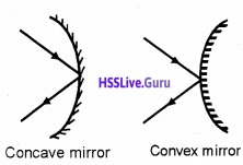
Reflection of light: Spherical mirrors are of two types.

  • Concave mirror
  • Convex mirror

Plus Two Physics Notes Chapter 9 Ray Optics and Optical Instruments - 2
Principal focus of a concave mirror:
Plus Two Physics Notes Chapter 9 Ray Optics and Optical Instruments - 3
A narrow parallel beam of light, parallel and close to the principal axis, after reflection converges to a fixed point on the principal axis is called principal focus of concave mirror.
Principal focus of a convex mirror:
Plus Two Physics Notes Chapter 9 Ray Optics and Optical Instruments - 4
A narrow parallel beam of light, parallel and close to the principal axis, after reflection appears to diverge from a point on the principal axis is called principal focus of convex mirror.
Relation connecting focal length and radius of curvature:
Plus Two Physics Notes Chapter 9 Ray Optics and Optical Instruments - 5
Consider a ray AB parallel to principal axis incident on a concave mirror at point B and is reflected along BF. The line CB is normal to the mirror as shown in the figure.
Let θ be angle of incidence and reflection.
Draw BD ⊥ CP,
In right angled ΔBCD,
Tanθ = \(\frac{B D}{C D}\) _____(1)
In right angled ΔBFD,
Tan2θ = \(\frac{B D}{F D}\) _____(2)
Dividing (1)and(2)
\(\frac{\tan 2 \theta}{\tan \theta}=\frac{C D}{F D}\) ____(3)
If θ is very small, then tanθ ≈ θ and tan2θ ≈ 2θ
The point B lies very close to P. Hence CD ≈ CP and FD ≈ FP From (3) we get
Plus Two Physics Notes Chapter 9 Ray Optics and Optical Instruments - 6

Plus Two Physics Notes Chapter 9 Ray Optics and Optical Instruments

3. The mirror equation:
Plus Two Physics Notes Chapter 9 Ray Optics and Optical Instruments - 7
Let points P, F, C be pole, focus, and centre of curvature of a concave mirror. Object AB is placed on the principal axis. A ray from AB incident at E and then reflected through F. Another ray of light from B incident at pole P and then reflected. These two rays meet at M. The ray of light from point B is passed through C. Draw EN perpendicular to the principal axis.
ΔIMF and ΔENF are similar.
ie. \(\frac{I M}{N E}=\frac{I F}{N F}\) _____(1)
but IF = PI – PF and NF = PF (since aperture is small)
hence eq. (1) can be written as
Plus Two Physics Notes Chapter 9 Ray Optics and Optical Instruments - 8
[∵ NE = AB)
ΔABP and ΔIMP are similar
Plus Two Physics Notes Chapter 9 Ray Optics and Optical Instruments - 9
From eq.(2) and eq.(3), we get
Plus Two Physics Notes Chapter 9 Ray Optics and Optical Instruments - 11

Plus Two Physics Notes Chapter 9 Ray Optics and Optical Instruments
applying sign convention we get
PI = -v
PF = -F
PA = -u
Substituting these values in eq.(4) we get
Plus Two Physics Notes Chapter 9 Ray Optics and Optical Instruments - 12
This is called mirror formula or mirror equation.
Linear magnification:
Linear magnification is defined as the ratio of the height of the image to the height of the object.
Plus Two Physics Notes Chapter 9 Ray Optics and Optical Instruments - 13
Consider an object AB having height ho, which produces an image IM having height hi
In the figure, ΔABP and ΔIMP are equal. ie.
Plus Two Physics Notes Chapter 9 Ray Optics and Optical Instruments - 14
Applying sign convention
PI = -V, PA = -u, hi = -ve and ho = +ve
We get
Plus Two Physics Notes Chapter 9 Ray Optics and Optical Instruments - 15
But we know \(\frac{h_{i}}{h_{0}}\) = m (magnification) ie.
Plus Two Physics Notes Chapter 9 Ray Optics and Optical Instruments - 16

Plus Two Physics Notes Chapter 9 Ray Optics and Optical Instruments
This formulae is true fora concave mirror and convex mirror.
Relation connecting v, f, and m
We have
\(\frac{1}{u}+\frac{1}{v}=\frac{1}{f}\)
Multiplying throughout by ‘v’, we get
\(\frac{v}{u}+\frac{v}{v}=\frac{v}{f}\)
But m = -v/u
ie. -m + 1 = \(\frac{v}{f}\)
m = 1 – \(\frac{v}{f}\)
Plus Two Physics Notes Chapter 9 Ray Optics and Optical Instruments - 17
Relation connecting u, f and m
We know
\(\frac{1}{u}+\frac{1}{v}=\frac{1}{f}\)
Multiplying throughout by ‘u’ we get
Plus Two Physics Notes Chapter 9 Ray Optics and Optical Instruments - 18

Refraction
The phenomenon of bending of light when it travels from one medium to another is known as refraction.
Light from rarer to denser medium:
Plus Two Physics Notes Chapter 9 Ray Optics and Optical Instruments - 19
When light travels from a rarer medium to a denser medium, it deviates towards the normal.
Light from denser to rarer medium:
Plus Two Physics Notes Chapter 9 Ray Optics and Optical Instruments - 20
When light travels from a denser medium to a rarer medium, it deviates away from the normal.

Plus Two Physics Notes Chapter 9 Ray Optics and Optical Instruments

Laws of refraction:
First law:
The incident ray, the refracted ray, and the normal at the point of incidence are all in the same plane.

Second law (Snell’s law):
The ratio of the sine of the angle of incidence to the sine of the angle of refraction is a constant for a given pair of media and for the given colour of light used. This constant is known as the refractive index of second medium w.r. t. the first medium.

Explanation:
If ‘i’ is the angle of incidence in the first medium and ‘r’ is the angle of refraction in the second medium, then by Snell’s law,
Plus Two Physics Notes Chapter 9 Ray Optics and Optical Instruments - 21
Where 1n2 is the refractive index of the second medium with respect to the first medium. If the first medium is air, then sini/sinr is known as absolute refractive index of the second medium.
ie, \(\frac{\sin i}{\sin r}=n\)
where ‘n’ is the refractive index of the second medium.

Some examples of refraction:
(a) Apparent depth:
Plus Two Physics Notes Chapter 9 Ray Optics and Optical Instruments - 22
When an object (in a denser medium) is viewed from a rarer medium, it seems to be raised towards the surface. This is called apparent depth.

(b) Twinkling of stars:
Twinkling of stars is due to the refraction of star light at different layers of the atmosphere. Due to this refraction the star at S appears at S1. But the density of the layer continuously changes. So, the apparent position continuously changes. Thus the star appears to be twinkling.
Plus Two Physics Notes Chapter 9 Ray Optics and Optical Instruments - 23

Plus Two Physics Notes Chapter 9 Ray Optics and Optical Instruments

(c) Apparent shift in the position of the sun at sunrise and sunset:
Plus Two Physics Notes Chapter 9 Ray Optics and Optical Instruments - 26
Sun is visible before sunrise and after sunset because of atmospheric refraction. The density of atmospheric air decreases as we go up. So the rays coming from the sun deviates towards the normal. So the sun at ‘S’ appears to come from ‘S1’. Thus an observer on earth can see the sun before sunrise and after sunset.

Total Internal Reflection
Plus Two Physics Notes Chapter 9 Ray Optics and Optical Instruments - 27
When a ray of light passes from a denser to rarer medium, after refraction the ray bends away from the normal. If the angle of incidence increases, the angle of refraction increases. When the angle of refraction is 90°, the corresponding angle of incidence is called the critical angle.

If we increases the angle of incidence beyond the critical angle, the ray is totally reflected back to the same medium. This phenomenon is called total internal reflection.

Relation between critical angle and refractive index
Refractive index,
Plus Two Physics Notes Chapter 9 Ray Optics and Optical Instruments - 28
where ‘C’ is the critical angle.
A demonstration for total internal reflection
Demonstration – 1:
Plus Two Physics Notes Chapter 9 Ray Optics and Optical Instruments - 29
Take a soap solution in a beaker. Now direct the laser beam from one side of the beaker such that it strikes the upper surface of water obliquely. Adjust the direction of laser beam until the beam is totally reflected back to water.

Demonstration – 2:
Plus Two Physics Notes Chapter 9 Ray Optics and Optical Instruments - 30

Plus Two Physics Notes Chapter 9 Ray Optics and Optical Instruments
Take a soap solution in a long test tube and shine the laser light from top, as shown in above figure. Adjust the direction of the laser beam such that it is totally internally reflected. This is similar to what happens in optical fibres.
Condition for total internal reflection:

  1. Light should travel from denser medium to rarer medium.
  2. Angle of incidence in the denser medium should be greater than the critical angle.

Relative critical angle:
Critical angle of a medium A with respect to a rarer medium B is represented as BCA. BCA is related to the refractive index BnA as
Plus Two Physics Notes Chapter 9 Ray Optics and Optical Instruments - 31

Some Effects And Applications Of Total Internal Reflection
(a) Brilliance of diamond:
Refractive index of diamond is high (n = 2.42) and the critical angle is small (C = 24.41°). More over the faces of the diamond are cut in such a way that a ray of light entering the crystal undergoes multiple total reflections. This multiple reflected light come out through one or two faces. So these faces appear glittering.

(b) Mirage:
On hot summer days the layer of air in contact with the sand becomes hot and rare. The upper layers are comparatively cooler and denser. When light rays travel from denser to rarer, they undergo total internal reflection. Thus image of the distant object is seen inverted. This phenomenon is Known as mirage.

(c) Looming (superior mirage):
Due to the mist and fog in cold countries, distant ship cannot be seen clearly. But due to the total internal reflection, the image of the ship appears hanging in air. This illusion is known as looming.

(d)Total reflection prisms:
Plus Two Physics Notes Chapter 9 Ray Optics and Optical Instruments - 32
A right-angled prism is called a total reflecting prisms. Total reflecting prisms are based on the principle of total internal reflection. With the help of these prisms, the direction of the incident ray can be changed. The refractive index for glass is 1.5 and its critical angle is 42°. When a ray of light makes an angle of incident more than 42° (within the glass) the ray undergoes total internal reflection.

1. Optical fibres:
Plus Two Physics Notes Chapter 9 Ray Optics and Optical Instruments - 33
Optical fibres consist of a number of long fibres made of glass or quartz (n = 1.7). They are coated with a layer of a material of lower refractive index (1.5). When light incident on the optical fibre at angle greater than the critical angle, it undergoes total internal reflection. Due to this total internal reflection, a ray of light can travel through a twisted path.
Uses:

  • Used as a light pipe in medical and optical diagnosis.
  • It can be used for optical signal transmissions.
  • Used to carry telephone, television and computer signals as pulses of light.
  • Used for the transmission and reception of electrical signals which are converted into light signals.

Plus Two Physics Notes Chapter 9 Ray Optics and Optical Instruments

Refraction At Spherical Surfaces And By Lenses
Spherical lenses:
There are two types of lenses

  • convex lenses and
  • concave lenses.

Plus Two Physics Notes Chapter 9 Ray Optics and Optical Instruments - 34
Principal axis:
A straight line passing through the two centers of curvature is called the principal axis of the lens.

Principal focus (F):
A narrow beam of parallel rays, parallel and close to the principal axis, after refraction, converges to a point on the principal axis in the case of a convex lens or appears to diverge from a point on the axis in the case of a concave lens. This fixed point is called the principal focus of the lens.

Focal length:
It is distance between the optic centre and the principal focus.

1. Refraction at a spherical surface:
Plus Two Physics Notes Chapter 9 Ray Optics and Optical Instruments - 35
Consider a convex surface XY, which separates two media having refractive indices n1 and n2. Let C be the centre of curvature and P be the pole. Let an object is placed at ‘O’, at a distance ‘u’ from the pole. I is the real image of the object at a distance V from the surface. OA is the incident ray at angle ‘i’ and Al is the refracted ray at an angle ‘r’. OP is the ray incident normally. So it passes without any deviation. From snell’s law,
Plus Two Physics Notes Chapter 9 Ray Optics and Optical Instruments - 36
r1 = n2 _____(1)
From the Δ OAC, exterior angle = sum of the interior opposite angles
i.e., i = α + θ ______(2)
Similarly, from ΔIAC,
a = α + β
r = α – β ______(3)
Substituting the values of eq(2) and eq(3)in eqn.(1) we get,
n1(α + θ) = n2(α – β)
n1α + n1θ = n2α – n2β
n1θ + n2β = n2α – n1α
n1θ + n2β = (n2 – n1)α _______(4)
From OAP, we can write,
Plus Two Physics Notes Chapter 9 Ray Optics and Optical Instruments - 37

Plus Two Physics Notes Chapter 9 Ray Optics and Optical Instruments
From IAP, β = \(\frac{\mathrm{AP}}{\mathrm{PI}}\), From CAP, α = \(\frac{\mathrm{AP}}{\mathrm{PC}}\)
Substituting θ, β and α in equation (4) we get,
Plus Two Physics Notes Chapter 9 Ray Optics and Optical Instruments - 38
According to New Cartesian sign convection, we can write,
OP = -u, PI = +v and PC = R
Substituting these values, we get
Plus Two Physics Notes Chapter 9 Ray Optics and Optical Instruments - 39
Case -1: If the first medium is air, n1 = 1, and n2 = n,
Plus Two Physics Notes Chapter 9 Ray Optics and Optical Instruments - 40

2. Refraction by a lens:
Lens Maker’s Formula (for a thin lens):
Consider a thin lens of refractive index n2 formed by the spherical surfaces ABC and ADC. Let the lens is kept in a medium of refractive index n1 Let an object ‘O’ is placed in the medium of refractive index n1 Hence the incident ray OM is in the medium of refractive index n1 and the refracted ray MN is in the medium of refractive index n2.
Plus Two Physics Notes Chapter 9 Ray Optics and Optical Instruments - 41
The spherical surface ABC (radius of curvature R1) forms the image at I1. Let ‘u’ be the object distance and ‘v1‘ be the image distance.
Then we can write,
Plus Two Physics Notes Chapter 9 Ray Optics and Optical Instruments - 42
This image I1 will act as the virtual object for the surface ADC and forms the image at v.
Then we can write,
Plus Two Physics Notes Chapter 9 Ray Optics and Optical Instruments - 43
Adding eq (1) and eq (2) we get
Plus Two Physics Notes Chapter 9 Ray Optics and Optical Instruments - 44

Plus Two Physics Notes Chapter 9 Ray Optics and Optical Instruments
Dividing throughout by n1, we get
Plus Two Physics Notes Chapter 9 Ray Optics and Optical Instruments - 45
if the lens is kept in air, \(\frac{\mathrm{n}_{2}}{\mathrm{n}_{1}}\) = n
So the above equation can be written as,
Plus Two Physics Notes Chapter 9 Ray Optics and Optical Instruments - 46
From the definition of the lens, we can take, when u = 8, f = v
Substituting these values in the eq (3), we get
Plus Two Physics Notes Chapter 9 Ray Optics and Optical Instruments - 47
This is lens maker’s formula
Plus Two Physics Notes Chapter 9 Ray Optics and Optical Instruments - 48
For convex lens,
f = +ve, R1 = +ve, R2 = – ve
Plus Two Physics Notes Chapter 9 Ray Optics and Optical Instruments - 49
For concave lens,
f = -ve, R1 = -ve, R2 = +ve
Plus Two Physics Notes Chapter 9 Ray Optics and Optical Instruments - 50
Lens formula
Plus Two Physics Notes Chapter 9 Ray Optics and Optical Instruments - 51
Linear magnification: If ho is the height of the object and hi is the height of the image, then linear magnification
Plus Two Physics Notes Chapter 9 Ray Optics and Optical Instruments - 52

3. Power of a lens:
Power of a lens is the reciprocal of focal length expressed in meter.
Plus Two Physics Notes Chapter 9 Ray Optics and Optical Instruments - 53

Plus Two Physics Notes Chapter 9 Ray Optics and Optical Instruments
Unit of power is dioptre (D).

4. Combination of thin lenses in contact:
Plus Two Physics Notes Chapter 9 Ray Optics and Optical Instruments - 54
Consider two thin convex lenses of focal lengths f1 and f2 kept in contact. Let O be an object kept at a distance ‘u’ from the first lens L1, I1 is the image formed by the first lens at a distance v1.
Then from the lens formula, we can write,
Plus Two Physics Notes Chapter 9 Ray Optics and Optical Instruments - 55
This image will act as the virtual object for the second lens and the final image is formed at I (at a distance v). Then
Plus Two Physics Notes Chapter 9 Ray Optics and Optical Instruments - 56
If the two lenses are replaced by a single lens of focal length ‘F’ the image is formed at V. Then we can write,
Plus Two Physics Notes Chapter 9 Ray Optics and Optical Instruments - 57
where P is the power of the combination, P1 and P2 are the powers of the individual lenses.

Magnification (combination of lenses):
If m1, m2, m3,…….. are the magnification produced by each lens,
then the net magnification,
m = m1. m2. m3……….
Relation connecting m, u and f:
Plus Two Physics Notes Chapter 9 Ray Optics and Optical Instruments - 58

Plus Two Physics Notes Chapter 9 Ray Optics and Optical Instruments
Relation connecting m,v and f:
Plus Two Physics Notes Chapter 9 Ray Optics and Optical Instruments - 59
Plus Two Physics Notes Chapter 9 Ray Optics and Optical Instruments - 60

Refraction Through A Prism
Plus Two Physics Notes Chapter 9 Ray Optics and Optical Instruments - 61
ABC is a section of a prism. AB and AC are the refracting faces, BC is the base of the prism, ∠A is the angle of prism.
Aray PQ incidents on the face AB at an angle i1. QR is the refracted ray inside the prism, which makes two angles r1 and r2 (inside the prism). RS is the emergent ray at angle i2.
The angle between the emergent ray and incident ray is the deviation ‘d’.
In the quadrilateral AQMR,
∠Q + ∠R = 180°
[since and N1M are normal] ie,
∠A + ∠M = 180° ____(1)
In the Δ QMR.
∴ r1 + r2 + ∠M = 180° _____(2)
Comparing eq (1) and eq (2)
r1 + r2 = ∠A ______(3)
From the Δ QRT,
(i1 – r1) + (i2 – r2) = d
[since exterior angle equal sum of the opposite interior angles]
(i1 + i2) – (r1 + r2) = d
but, r1 + r2 =A
∴ (i1 + i2 ) – A = d
(i1 + i2) = d + A _____(4)

Plus Two Physics Notes Chapter 9 Ray Optics and Optical Instruments
It is found that for a particular angle of incidence, the deviation is found to be minimum value ‘D’.
At the minimum deviation position,
i1 = i2 = i, r1 = r2 = r and d = D
Hence eq (3) can be written as,
r + r= A
or r = \(\frac{A}{2}\) ______(5)
Similarly eq (4) can be written as,
i + i = A + D
i = \(\frac{A+D}{2}\) _____(6)
Let n be the refractive index of the prism, then we can write,
n = \(\frac{\sin i}{\sin r}\) ______(7)
Substituting eq (5) and eq (6) in eq (7),
Plus Two Physics Notes Chapter 9 Ray Optics and Optical Instruments - 62
i – d curve:
Plus Two Physics Notes Chapter 9 Ray Optics and Optical Instruments - 63
It is found that when the angle of incidence increases deviation (d) decreases and reaches a minimum value and then increases. This minimum value of the angle of deviation is called the angle of minimum deviation.

Plus Two Physics Notes Chapter 9 Ray Optics and Optical Instruments

Dispersion By A Prism
Dispersion: The splitting of the white light into its component colours is called dispersion.
Plus Two Physics Notes Chapter 9 Ray Optics and Optical Instruments - 64
The pattern of colour components of light is called the spectrum of light.

Reason for dispersion:
The refractive index is different for different colours. Refractive index for violet is higher than red. This variation of refractive index of medium with the wavelength causes dispersion.

Some Natural Phenomena Due To Sunlight
1. The rainbow:
The rainbow is an example of the dispersion of sunlight by the water drops in the atmosphere. The conditions for observing a rainbow are that the sun should be shining in one part of the sky while it is raining in the opposite part of the sky.
There are two types rainbow

  • Primary rainbow
  • secondary rainbow.

(i) Primary rainbow:
Plus Two Physics Notes Chapter 9 Ray Optics and Optical Instruments - 65
In a primary rainbow, after refraction at the surface of water droplet, the ray suffers one internal reflection and finally comes out of the drop by forming an inverted spectrum. The maximum deviated light is red (42°) and the least deviated light is violet (40°).

(ii) Secondary rainbow:
Plus Two Physics Notes Chapter 9 Ray Optics and Optical Instruments - 66
secondary rainbow, after refraction at the surface of water droplet, the ray suffers two total internal reflection and finally comes out of the droplet by forming a spectrum. The most deviated light in this spectrum is violet (53°) and the least deviated light is red (50°).

2. Scattering of light:
When sunlight travels through the earth’s atmosphere, it changes its direction by atmospheric particles. This is called scattering. Light of shorter wavelength is scattered much more than light of longer wavelength. Scattering is possible only when size of the particles is comparable to the wavelength of incident light.

Plus Two Physics Notes Chapter 9 Ray Optics and Optical Instruments

Rayleigh’s scattering law:
The intensity of the scattered light from a molecule is inversely proportional to the 4th power of the wavelength.
ie, \(I \alpha \frac{1}{\lambda^{4}}\)
I – Intensity of Scattering

Blue colour of sky:
According to Rayleigh scattering, scattering is inversely proportional to the fourth power of its wavelength. Hence shorterwavelength is scattered much more than longer wavelength. Thus blue colour is more scattered than the other colours. So sky appears blue.

Whiteness of clouds:
Clouds contain large partides (dust, H2O), which scatter all colours almost equally. Hence clouds appear white.

Colours of the sunset (or sunrise):
At sunrise and sunset light has to travel a longer distance before reaching the earth. During this time, smaller wavelengths are scattered away. The remaining colours is red. Hence sky appears red in colour.

Optical Instruments
Mirrors, lenses and prisms, periscope, Kaleidoscope, Binoculars, telescopes, microscopes are some examples of optical devices Our eye is one of the most important optical device.

1. The eye:
Plus Two Physics Notes Chapter 9 Ray Optics and Optical Instruments - 67
Human eye consists of an eyeball of size 2.5cm in diameter. The very thin skin in front of the eye is known as cornea. Behind cornea, the empty space is known as aqueous humor. The small wall behind cornea is known as iris. In this iris a small circular opening is there, which is known as pupil. Iris can adjust its tension to vary the size of the pupil.

Behind the iris a muscular membrane is there which is known as ciliary muscle. The focal length of the crystalline lens can be adjusted to see the object any separation by adjusting the tension of ciliary muscles. The backwall of eye is known as retina.

It consists of light sensitive cells known as rods and cones. The rods are sensitive to intensity and cones are sensitive to colour. The signals from retina are transferred to the brain by optic nerves.

The brightest point in the retina is known as yellow spot and the lowest point in the eye (retina) is known as blind spot. The space between the lens and retina is filled by a liquid which is known as vitreous humor.

Defects of Vision
a. Myopia or shortsightedness:
Plus Two Physics Notes Chapter 9 Ray Optics and Optical Instruments - 68

Plus Two Physics Notes Chapter 9 Ray Optics and Optical Instruments
A person suffering from myopia can see only nearby objects but cannot see objects beyond a certain distance clearly. This defect occurs due to

  1. Elongation of eyeball
  2. Short focal length of eye lens

It can be corrected by using a concave lens of suitable focal length.

b. Hypermetropia or Far sightedness:
Plus Two Physics Notes Chapter 9 Ray Optics and Optical Instruments - 69
A person suffering from this defect can see only distant object clearly but cannot see nearby objects clearly. This defect occurs due to

  1. Decrease in the size of the eyeball.
  2. Increase in focal length of the eyeball.

This defect can be corrected by using a converging lens (convex).

c. Astigmatism:
Plus Two Physics Notes Chapter 9 Ray Optics and Optical Instruments - 70
A person suffering from astigmatism cannot focus objects in front of the eye clearly. It can be corrected by using a cylindrical lens of suitable focal length.

d. Presbyopia:
It is the farsightedness occurring due to awakening of ciliary muscles. It can be corrected by using a lens of bifocal length.

Plus Two Physics Notes Chapter 9 Ray Optics and Optical Instruments

1. The microscope:
Simple microscope: A simple microscope is a converging lens of small focal length.
Plus Two Physics Notes Chapter 9 Ray Optics and Optical Instruments - 71
Working: The object to be magnified is placed very close to the lens and the eye is positioned close to the lens on the other side. Depending upon the position of object, the position of image is changed.

Case 1:
If the object is placed, one focal length away or less, we get an erect, magnified and virtual image at a distance so that it can be viewed comfortably ie. at 25cm or more. (This 25cm is denoted by the symbol D).

Case 2:
If the object is placed at a distance f (focal length of lens), we get the image at infinity.

Mathematical expression of magnification:
Image at D:
If the image is formed at ‘D’, we can take u = -D. Hence the lens formula can be written as
Plus Two Physics Notes Chapter 9 Ray Optics and Optical Instruments - 72
The image is formed at D, ie. v = -D
Plus Two Physics Notes Chapter 9 Ray Optics and Optical Instruments - 73
This equation is used to find magnification of simple microscope when image at D (D ≈ 25cm).

Image at infinity:
Plus Two Physics Notes Chapter 9 Ray Optics and Optical Instruments - 78

Plus Two Physics Notes Chapter 9 Ray Optics and Optical Instruments
If the object is placed at f, the image forms at infinity. In this case, magnification,
Plus Two Physics Notes Chapter 9 Ray Optics and Optical Instruments - 79
Suppose the object has a height h, the angle subtended is
tanθ0\(=\frac{h}{D}\), θ0\(=\frac{h}{D}\)______(2)
where ‘D’ is the comfortable distance of object from the eye (least distinct vision).
Plus Two Physics Notes Chapter 9 Ray Optics and Optical Instruments - 80
When the final image is formed at infinity,
θi = \(\frac{h^{1}}{v}\) ______(3)
When h1 is the height of image and v is the image distance
Plus Two Physics Notes Chapter 9 Ray Optics and Optical Instruments - 81
This equation is used to find magnification of simple microscope when image at infinity.

2. Compound microscope:
Apparatus: A compound microscope consists of two convex lenses, one is called the objective and the other is called eye piece.

The convex lens near to the object is called objective. The lens near to the eye is called eye piece. The two lenses are fixed at the ends of two co-axial tubes. The distance between the tubes can be adjusted.
Plus Two Physics Notes Chapter 9 Ray Optics and Optical Instruments - 82

Plus Two Physics Notes Chapter 9 Ray Optics and Optical Instruments
Working:
The object is placed in between F and 2F of objective lens. The objective lens forms real inverted and magnified image (I1M1) on the other side of the lens.

This image will act as object or eyepiece. Thus an enlarged, virtual, and inverted image is formed, (this image can be adjusted to be at the least distance of distinct vision, D).

Magnification: The magnification produced by the compound microscope
Plus Two Physics Notes Chapter 9 Ray Optics and Optical Instruments - 83
Where m0 & me are the magnifying power of objective lens and eyepiece lens.
Plus Two Physics Notes Chapter 9 Ray Optics and Optical Instruments - 84
Eyepiece acts as a simple microscope.
Therefore me = 1 + \(\frac{D}{f_{e}}\) _____(2)
m0 = \(\frac{v_{0}}{u_{0}}\) ______(3)
We know magnification of objective lens
Where v0 and u0 are the distance of the image and object from the objective lens.
Substituting (2) and (3) in (1), we get
Plus Two Physics Notes Chapter 9 Ray Optics and Optical Instruments - 85
for compound microscope, uo » fo (because the object of is placed very close to the principal focus of the objective) and vo ≈ L, length of microscope (because the first image is formed very close to the eye piece).
Plus Two Physics Notes Chapter 9 Ray Optics and Optical Instruments - 86
where L is the length of microscope, f0 is the focal length of objective lens.
Case 1: If the final image is formed at infinity, magnification of eye piece D
m \(=\frac{D}{f_{e}}\)
∴ Total magnification of compound microscope
Plus Two Physics Notes Chapter 9 Ray Optics and Optical Instruments - 87

Plus Two Physics Notes Chapter 9 Ray Optics and Optical Instruments

(3) Telescope: Astronomical telescope is used to observe heavenly bodies.
There are two types of telescopes

  1. Refracting and
  2. Reflecting Telescope.

(1) Refracting Telescope:
Constructional details
Plus Two Physics Notes Chapter 9 Ray Optics and Optical Instruments - 88
It consists of two convex lenses, one is called objective and other is called eyepiece. These two lenses are fitted at the ends of two coaxial tubes. The distance between the two lenses can be varied.

Working:
The objective lens forms the image (IM) of a distant object at its focus. This image (formed by objective) is adjusted to be focus of the eyepiece.

Magnification:
The magnifying power of a telescope is the ratio of the angle subtended by the image at the eye to the angle subtended by the object at the objective.
Plus Two Physics Notes Chapter 9 Ray Optics and Optical Instruments - 89

Plus Two Physics Notes Chapter 9 Ray Optics and Optical Instruments
(For small values tan α ≈ α)
Plus Two Physics Notes Chapter 9 Ray Optics and Optical Instruments - 90
But IC = fo (the focal length objective lens) and IC1 = fe(the focal length eyepiece lens.)
∴ m = \(\frac{f_{0}}{f_{e}}\)
In this case the length of the telescope tube is (f0 + fe).

Case 1: When the image formed by the objective is within the focal length of the eyepiece, Then the final image is formed at the least distant of distinct vision. In this case, magnifying power.
Plus Two Physics Notes Chapter 9 Ray Optics and Optical Instruments - 91

(2) Reflecting Telescope:
Newtonian types reflecting Telescope:
The Newtonian reflector consists of a parabolic mirror made of an alloy of copper and tin. It is fixed atone end of a metal tube.

The parallel rays from a distant stars incident on the mirror M1. After reflection from the mirror, the ray incident on a plane mirror M2.

Plus Two Physics Notes Chapter 9 Ray Optics and Optical Instruments

The reflected ray from M2 enter into eye piece E. The eyepiece forms a magnified, virtual and erect image. Magnifying power of Newton Telescope
m = \(\frac{f_{0}}{f_{e}}\) or m = \(\frac{R}{2 f_{\theta_{g}}}\)
where
fo — is the focal length of concave mirror
f2 — is the focal length of eyepiece.
R – Radius of curvature of concave reflector.

Plus One Botany Notes Chapter 7 Transport in Plants

Students can Download Chapter 7 Transport in Plants Notes, Plus One Botany Notes helps you to revise the complete Kerala State Syllabus and score more marks in your examinations.

Kerala Plus One Botany Notes Chapter 7 Transport in Plants

Translocation:
It is the transport over longer distances takes place through the vascular system (the xylem and the phloem)

Means of transport:
Diffusion:

  • It is passive process takes place from the regions of higher concentration to regions of lower
  • Diffusion is a slow process and is not dependent on a ‘living system’, it mainly occurs in gases and liquids.
  • Diffusion is very important to plants for gaseous movement within the plant body.

Plus One Botany Notes Chapter 7 Transport in Plants

Rate of diffusion:
Factors influencing diffusion are

  1. Gradient of concentration
  2. The permeability of the membrane separating them
  3. Temperature and pressure.

Facilitated Diffusion:
Substances that have a hydrophilic moiety difficult to pass through the membrane, their movement to be facilitated by protein.
Plus One Botany Notes Chapter 7 Transport in Plants 1
What is the requirement for facilitated diffusion?

  • Special membrane proteins help the movement of substances across membranes
  • Movement of substance takes place without the expenditure of ATP or energy.

Rate of facilitated diffusion:
The diffusion rate depends on the

  1. size of the substances.
  2. solubility in lipids

Features:

  1. Substances soluble in lipids diffuse through the membrane faster.
  2. It is specific and allows the cell to select substances for uptake.
  3. It is sensitive to inhibitors which react with protein side chains.
  4. Transport rate reaches a maximum when all of the protein transporters are being used (saturation).
  5. The proteins form channels in the membrane. Some channels are always open others can be controlled

Nature of transport protein:
1. The porins are proteins that form huge pores in the outer membranes of the plastids, mitochondria and some bacteria that allowing molecules up to the size of small proteins to pass through.

2. Some of the transport protein rotates and releases the molecule inside the cell, eg: water channels – made up of eight different types of aquaporins.

Plus One Botany Notes Chapter 7 Transport in Plants 2

Plus One Botany Notes Chapter 7 Transport in Plants

Passive symports, antiports and uniport:

  1. In a symport, both molecules cross the membrane in the same direction with help of carrier or transport proteins.
  2. In an antiport, they move in opposite directions.
  3. When a molecule moves across a membrane independent of other molecules, the process is called uniport.

Active Transport:
Active transport is a uphill process why?

  • Proteins transport substances from a low concentration to a high concentration (‘uphill’ transport) by using energy
  • It is carried out by membrane-proteins.
  • Transport rate reaches a maximum when all the protein transporters are being used or are saturated.
  • This carrier protein is very specific in transport and sensitive to inhibitors that react with protein side chains.

Comparison of Different Transport Processes:

  • Proteins in the membrane show common characteristics of being highly selective; they are liable to saturate, respond to inhibitors and are under hormonal regulation.
  • But diffusion whether facilitated or not take place only along a gradient and do not use energy.

Plus One Botany Notes Chapter 7 Transport in Plants 3

Plant- Water relations:

  • Water is the medium in which most substances are dissolved.
  • The protoplasm of the cell contains water in which different molecules are dissolved and suspended.
  • A watermelon has over 92 percent water; most herbaceous plants have only about 10 to 15 percent of its fresh weight as dry matter.
  • Terrestrial plants take up huge amount water daily but most of it is lost to the air through evaporation from the leaves, i.e., transpiration.
  • A mature corn plant absorbs almost three litres of water in a day, while a mustard plant absorbs water equal to its own weight in about 5 hours.
  • Water is the limiting factor for plant growth and productivity.

Plus One Botany Notes Chapter 7 Transport in Plants

Water Potential:

  • It is the sum of Solute potential and pressure potential.
    • \(\Psi_{w}=\Psi_{x}+\Psi_{p}\)
  • Water potential is denoted by the Greek symbol Psi.
  • It is expressed in pressure units such as pascals (Pa).

Solution have a lower water potential than pure water why?
When solute dissolves water potential is decreased called solute potential (negative sign)

  • Water molecules possess kinetic energy. The greater the concentration of water in a system, the greater is its kinetic energy or ‘water potential’.
  • Water move from the higher water potential to the lower water potential.

How can increase water potential?

  • If a pressure greater than atmospheric pressure is applied to pure water or a solution, its water potential increases
  • Water enters a plant cell due to diffusion causing a pressure built up against the cell wall, it makes the cell turgid, this increases the pressure potential. (sign is positive)
  • Water potential of a cell is affected by both solute and pressure potential.
For a solution at atmospheric pressure (water potential) = (solute potential)
Pure water have the greatest water potential. It is taken as zero.

Osmosis:
It is the diffusion of water across the semi-permeable membrane.
Rate of osmosis: It is influenced by

  • pressure gradient
  • concentration gradient.

1. In plant cells, the cell membrane the membrane of the vacuole (tonoplast) are together determines the movement of molecules in or out of the cell.

2. Water flows from its region of higher chemical potential (or concentration) to its region of lower chemical potential until equilibrium is reached.

3. At equilibrium the two chambers should have the same water potential.
Plus One Botany Notes Chapter 7 Transport in Plants 4

Plus One Botany Notes Chapter 7 Transport in Plants

Experiment to demonstrate osmosis:
1. In potato osmometer experiment, the tuber is placed in water the cavity in the potato tuber containing a concentrated solution of sugar collects water due to osmosis.

2. In thistle funnel experiment, sucrose solution in a funnel is separated from pure water in a beaker through a semi-permeable membrane .After some time water will move into the funnel resulting in rise in the level of the solution in the funnel. This will continue till the equilibrium is reached.

Reverse osmosis:
If an external pressure is applied from the upper part of the funnel, no water diffuses into the funnel through the membrane.
1. This pressure required to prevent water from diffusing is the osmotic pressure and this is the function of the solute concentration.

2. If increasing the solute concentration, the greater pressure is required to prevent water from diffusing in. Osmotic pressure is the positive pressure applied, while osmotic potential is negative.

3. A demonstration of osmosis. A thistle funnel is filled with sucrose solution and kept inverted in a beaker containing water, (a) Water will diffuse across the membrane (as shown by arrows) to raise the level of the solution in the funnel (b) Pressure can be applied as shown to stop the water movement into the funnel.
Plus One Botany Notes Chapter 7 Transport in Plants 5

Plasmolysis:
Importance of hypertonic solution:
When a cell is placed in a hypertonic solution water moves out due exosmosis, it causes the protoplast to shrink away from the walls. This is called plasmolysis. The cell become flaccid in state. The process of plamolysis is usually reversible.
Plus One Botany Notes Chapter 7 Transport in Plants 6

Cells become turgid state in pure water?
When the cells are placed in a hypotonic solution (higher water potential or dilute solution as compared to the cytoplasm), water diffuses into the cell due to endosmosis causing the cytoplasm to build up a pressure against the wall, that is called turgor pressure.

Isotonic solution:
If the external solution balances the osmotic pressure of the cytoplasm,it is said to be isotonic. When the cell (or tissue) is placed in an isotonic solution, there is no net flow of water towards the inside or outside. If the external solution is more dilute than the cytoplasm, it is hypotonic, cells swell in hypotonic solutions and shrink in hypertonic ones.

Plus One Botany Notes Chapter 7 Transport in Plants

Imbibition:
Imbibition is a special type of diffusion when water is absorbed by hydrophilic colloids and increase in volume.
Examples of imbibition:

  1. Absorption of water by seeds and dry wood
  2. Emerging out of seedlings from the soil

Water potential gradient between the absorbent and the liquid imbibed is essential for imbibition.

Long distance transport of water:

  • Mass flow is the movement of substances in bulk or en masse from one point to another as a result of pressure differences between the two points.
  • The bulk movement of substances through the conducting or vascular tissues of plants is called translocation.
  • Xylem is associated with translocation of water, mineral salts, some organic nitrogen and hormones, from roots to the aerial parts of the plants.
  • Phloem translocates organic and inorganic solutes, mainly from the leaves to other parts of the plants.

How do Plants Absorb Water?
Water is absorbed along with mineral solutes move deeper into root layers by two distinct pathways.
1. Apoplast pathway:

  • The apoplastic movement of water occurs exclusively through the intercellular spaces and the walls of the cells except at the casparian strips of the endodermis in the roots.
  • The apoplast does not provide any barrier to water movement and water movement is through mass flow i.e tension develop in the continuous stream of water in the apoplast due to the adhesive and cohesive properties of water

Plus One Botany Notes Chapter 7 Transport in Plants 7

2. Symplast pathway:

  • In symplastic movement the water travels through the cytoplasm of the cells
  • This intercellular movement takes place through the plasmodesmata. ‘Symplastic movement is aided by cytoplasmic streaming.
  • eg: cytoplasmic streaming in cells of the Hydrilla leaf; the movement of chloroplast due to streaming is easily visible.

Plus One Botany Notes Chapter 7 Transport in Plants 8

Plus One Botany Notes Chapter 7 Transport in Plants

Apoplastic pathway is not always continuous through cell wall why?
Apoplastic pathway is continuous upto the inner boundary of the cortex, the endodermis, is impervious,to water because of a band of suberised matrix called the casparian strip.

The water then moves through the symplast and again crosses a membrane to reach the cells of the xylem. This is the only way water and other solutes can enter the vascular cylinder.

Additional structures in water and mineral absorption:
1. A mycorrhiza is a symbiotic association of a fungus with a root system. The hyphae have a very large surface area that absorb mineral ions and water from the soil. The fungus provides minerals and water to the roots, in turn the roots provide sugars and N-containing compounds to the mycorrhizae.

2. Some plants have an obligate association with the mycorrhizae. For example, Pinus seeds cannot germinate and establish without the presence of mycorrhizae.

Water Movement up a Plant:
Root Pressure:

  • As various ions from the soil are actively transported into the vascular tissues of the roots, water flows (its potential gradient) and increases the pressure inside the xylem.
  • This positive pressure is called root pressure.
  • It helps to pushing up water to small heights.

Experiment to demonstrate root pressure:
When a small soft-stemmed plant is taken and cut the stem horizontally near the base with a sharp blade, early in the morning ,the drops of solution ooze out of the cut stem; this occurs due to positive root pressure.

When root pressure is high in herbaceous plants?
Effects of root pressure is also observable at night and early morning when evaporation is low, and excess water collects in the form of droplets around special openings of veins near the tip of grass blades, and leaves of many herbaceous parts.

Such water loss in its liquid phase is known as guttation. Root pressure do not play a major role in water movement up tall trees but it occurs in most plants by transpiratory pull

Transpiration pull:

  • Water is mainly ‘pulled’ through the plant with help of driving force – transpiration from the leaves referred to as the cohesion – tension – transpiration pull model of water transport.
  • Less than 1 percent of the water reaching the leaves is used in photosynthesis and plant growth.
  • Most of it is lost through the stomata in the leaves. This water loss is known as transpiration.

Plus One Botany Notes Chapter 7 Transport in Plants

Transpiration:
Transpiration is the evaporative loss of water occurs mainly through the stomata in the leaves.

  • Normally stomata are open in the day time and close during the night.
  • The opening or closing of the stomata is due to change in the turgidity of the guard cells.
  • The inner wall of each guard cell is thick and elastic.
  • When turgidity increases within the two guard cells the thin outer walls bulge out and opens the stoma. This is also aided due to the orientation of the microfibrils in the cell walls of the guard cells.
  • When the guard cells lose turgor, due to water loss (or water stress) the guard cells become flaccid and the stoma closes.

Plus One Botany Notes Chapter 7 Transport in Plants 9
Distribution of stomata in leaf:

  • The dorsiventral (often dicotyledonous) leaf has a greater number of stomata in the lower surface
  • Isobilateral (often monocotyledonous) leaf they are equally distributed on both surfaces.

Factors influencing transpiration:
External factors:
Temperature, light, humidity, wind speed

Plant factors:
Number and distribution of stomata, number of stomata open, per cent, water status of the plant, canopy structure, etc.

The transpiration driven ascent of xylem sap depends mainly on the following physical properties of water:

1. Cohesion: mutual attraction between water molecules.
2. Adhesion: attraction of water molecules to polar surfaces (such as the surface of tracheary elements).
3. Surface Tension: water molecules are attracted to each other in the liquid phase more than to water in the gas phase.
  • These properties give water high tensile strength, i.e., an ability to resist a pulling force, and high capillarity, i.e., the ability to rise in thin tubes.
  • In plants capillarity is aided by the small diameter of the tracheary elements – the tracheids and vessel elements
  • As water evaporates through the stomata results in pulling of water molecule by molecule, into the leaf from the xylem.
  • This occurs due to lower concentration of water vapour in the atmosphere as compared to the substomatal cavity and intercellular spaces, water diffuses into the surrounding air. This creates a ‘puli’.

Plus One Botany Notes Chapter 7 Transport in Plants 10

Plus One Botany Notes Chapter 7 Transport in Plants

Transpiration and Photosynthesis – a Compromise:
Advantageous of transpiration:

  1. creates transpiration pull for absorption and transport of plants
  2. supplies water for photosynthesis
  3. transports minerals from the soil to all parts of the plant
  4. cools leaf surfaces, sometimes 10 to 15 degrees, by evaporative cooling
  5. maintains the shape and structure of the plants by keeping cells turgid
  6. When water depleted by transpiration, photosynthesis is limited.
  7. The evolution of the C4 photosynthetic system maximising the availability of CO2 while minimising water loss.
  8. C4 plants are twice as efficient as C3 plants in terms of fixing carbon (making sugar). C4 plant loses only half as much water as a C3 plant for the same amount of CO2 fixed.

Uptake and transport of mineral nutrients: The nutritional requirements are obtained from minerals in the soil.
Uptake of Mineral Ions:
All minerals cannot be passively absorbed by the roots because

(i) minerals are present in the soil as charged particles (ions) which cannot move across cell membranes.
(ii) the concentration of minerals in the soil is usually lower than the concentration of minerals in the root. Therefore, most minerals must enter the root by active absorption. This needs energy in the form of ATP
  • The active uptake of ions is partly responsible for the water potential gradient in roots, and therefore for the uptake of water by osmosis.
  • Specific proteins in the membranes of root hair cells actively pump ions from the soil into the cytoplasm of the epidermal cells.
  • Root endodermis because of the layer of suberin has the ability to actively transport ions in one direction only.

Translocation of Mineral Ions:
Chiefsinks:

  1. Apical and lateral meristems
  2. young leaves
  3. developing flowers
  4. fruits and seeds
  5. the storage organs

Unloading of mineral ions occurs at the fine vein endings through diffusion and active uptake by these cells.

Mineral ions are frequently remobilized from older senescing parts to younger leaves. Some decidous plants, before leaf fall minerals are removed to other parts Mobilising elements are phosphorus, sulphur, nitrogen and potassium.
  • Some elements that are structural components like calcium are not remobilised.
  • An analysis of the xylem exudates shows that though more amount of nitrogen carried in the organic form as amino acids small amounts of P and S are carried as organic compounds.
  • Small amount of exchange of materials does take place between xylem and phloem.

Plus One Botany Notes Chapter 7 Transport in Plants

Phloem transport: flow from source to sink:
Phloem transport is bidirectional but xylom transport is unidirectional why?
Source is the part of the plant which synthesises the food. Sink is the part that needs or stores the food. Food ( sucrose) is transported by phloem from a source to a sink.lt is the downward transport Sugar stored in roots are mobilized to the buds of trees during early spring and act as sink.

This is called upward transport .Hence phloem transport is bi-directional. Phloem sap is mainly water and sucrose, but other sugars, hormones and amino acids are also transported or translocated through phloem. Xylem transport is always unidirectional, i.e. upwards.

The Pressure Flow or Mass Flow Hypothesis:
The accepted mechanism used for the translocation of sugars from source to sink is called the pressure flow hypothesis.
What is the loading of phloem?
The sugar is moved in the form of sucrose(a disaccharide) into the companion cells and then Tlpo!stem. into the living phloem sieve tube cells by active transport. This process is called loading. It produces a hypertonic condition in the phloem.

  • Phloem tissue is composed of sieve tube cells, which form long columns with holes in their end walls called sieve plates. ‘Cytoplasmic strands pass through the holes in the sieve plates,
  • Water in the adjacent xylem moves into the phloem by osmosis.
  • As hydrostatic pressure( Osmotic pressure) builds up in the in the phloem sieve tube, pressure flow begins and phloem sap move to areas of lower pressure
  • Active transport is necessary to move the sucrose out of the phloem sap and sugars are removed, the osmotic pressure decreases and water moves out of the phloem.
  • The loss of solute produces a high water potential in the phloem, and water passes out to xylem.

Plus One Botany Notes Chapter 7 Transport in Plants 11

Plus One Botany Notes Chapter 7 Transport in Plants

Girdling experiment:
It is used to identify the tissues through which food is transported. On the trunk of a tree a ring of bark up to a depth of the phloem layer is removed. In the absence of downward movement of food ,the portion of the bark above the ring on the stem becomes swollen after a few weeks.

This simple experiment shows that phloem is the tissue responsible for translocation of food and transport takes place in one direction, i.e., towards the roots.

Plus Two Physics Notes Chapter 8 Electromagnetic Waves

Students can Download Chapter 8 Electromagnetic Waves Notes, Plus Two Physics Notes helps you to revise the complete Kerala State Syllabus and score more marks in your examinations.

Kerala Plus Two Physics Notes Chapter 8 Electromagnetic Waves

Introduction
In this chapter we shall study the basic concepts of electromagnetic waves.

Displacement Current
Amperes circuital law in ac circuit: Consider a capacitor connected to a AC source using conducting wires. AC current can flow through a capacitor. Hence magnetic field is produced around the conducting wire. This magnetic field can be found using amperes circuital law.

Magnetic field at P
Method – 1 (To find magnetic field at P)
Plus Two Physics Notes Chapter 8 Electromagnetic Waves 1

Plus Two Physics Notes Chapter 8 Electromagnetic Waves
Consider a point P, which lies outside and very close to a capacitor as shown in the figure. We can find magnetic field at P using amperes circuital law. In order to find an magnetic field at P, consider a open surface (amperien loop having pot like surface) with a boundary of circle of radius r.
Applying amperes circuital law we get
\(\oint\)B.dI = µ0i
Where ‘i’ is the current passing through the surface. (This surface lies outside to capacitor)
Integrating we get B.2πr = µ0i
B = \(\frac{\mu_{0} i}{2 \pi r}\) _____(1)

Method – 2 (To find magnetic field at P)
Plus Two Physics Notes Chapter 8 Electromagnetic Waves 2
Consider a open surface (amperien loop having pot like surface) extended to interior of capacitor with a boundary of circle of radius r.
Applying amperes circuital law we get
\(\oint\)B.dI = µ00
(since the current passing through the closed surface is zero, surface lies in between the plates)
ie. B = 0 ______(2)

Discussion of method 1 and method 2: Amperian circuital law is independent of size and shape of pot like surface. Hence we expect same value of B in eq(1)and eq(2). But we got different values at the same point P. Hence we can understand that there is a mistake in the amperes circuital law in AC circuits.

Maxwells correction in amperes circuital law:
To solve the above mistake, Maxwell introduced a term in the amperes circuital law. The modified amperes circuital law can be written as
\(\oint\)B.dI = µ0(ic + id)
Where id is called displacement current. Its value is
Plus Two Physics Notes Chapter 8 Electromagnetic Waves 3

Plus Two Physics Notes Chapter 8 Electromagnetic Waves
The above modified amperes circuital is known as Ampere- Maxwell law. This law is applicable for both AC and DC circuits.

Question 1.
Show that conduction current ic is equal to displacement current id
Answer:
The flux passing through the surface in between plates (see figure 2)
Plus Two Physics Notes Chapter 8 Electromagnetic Waves 4
Capacitor is connected to ac voltage. Hence the charge on the plate also changes with time. Hence the flux passing through the pot shape surface changes with time.
ie. the flux in between capacitor changes.
The change influx,
Plus Two Physics Notes Chapter 8 Electromagnetic Waves 5

Plus Two Physics Notes Chapter 8 Electromagnetic Waves
This means that the conduction current passing through the conduction wire is converted into displacement current, when it passes in between plates of capacitor.
1. The total current i is the sum of the conduction current and the displacement current
So we have
Plus Two Physics Notes Chapter 8 Electromagnetic Waves 6

2. Outside the capacitor plates, we have only conduction current and no displacement current inside the capacitor there is no conduction current and there is only displacement current.

Electromagnetic Waves
1. Sources of Electromagnetic waves:
Question 2.
How are electromagnetic waves produced?
Answer:
Consider a charge oscillating with some frequency (An oscillating charge is an example of accelerating charge). This oscillation produces an oscillating electric and magnetic field in space. The oscillating electric and magnetic fields (EM Wave) propagates through the space. The experimental production of electromagnetic wave was done by Hertz’s experiment in 1887.

2. Nature of electromagnetic waves:
Characteristics of Electromagnetic waves:
(i) Electromagnetic waves propagate in the form of mutually perpendicular magnetic and electric
fields. The direction of propagation of wave is perpendicular to both magnetic and electric field vector.

(ii) Velocity of electromagnetic waves in free space is,
Plus Two Physics Notes Chapter 8 Electromagnetic Waves 7
The speed of electromagnetic wave in a material medium is given by
Plus Two Physics Notes Chapter 8 Electromagnetic Waves 8

Plus Two Physics Notes Chapter 8 Electromagnetic Waves

(iii) The ratio of magnitudes of electric and magnetic field vectors in free space is constant
Plus Two Physics Notes Chapter 8 Electromagnetic Waves 9
E and B are in same phase

(iv) No medium is required for propagation of transverse wave.

(v) Electromagnetic waves show properties of reflection, refraction, interference, diffraction and polarization.

(vi) Electromagnetic waves have capability to carry energy from one place to another.

Mathematical Expression:
Plus Two Physics Notes Chapter 8 Electromagnetic Waves 10
Consider a plane electromagnetic wave travelling along the Z direction. The electric and magnetic fields are perpendicular to the direction of wave motion.
The electric field vector along the Y direction.
Ex = E0sin(kz – ωt)
and BY = B0sin(kz – ωt)
where E0 is the amplitude of electric field vector, B0 is the amplitude of magnetic field vector, ω is the angular frequency and k is related to the wave length λ of the wave,
k = 2π/λ.

Plus Two Physics Notes Chapter 8 Electromagnetic Waves

Electromagnetic Spectrum
Electromagnetic waves include visible light waves, X-rays, gamma rays, radio waves, microwaves, ultraviolet and infrared waves. The classification is based roughly on how the waves are produced or detected.

1. Radio waves:
Radio waves are produced by the accelerated motion of charges in conducting wires. They are used in radio and television communication systems. They are generally in the frequency range from 500 kHz to about 1000 MHz.

2. Microwaves:
Microwaves (short-wavelength radio waves), with frequencies in the gigahertz (GHz) range, are produced by special vacuum tubes (called klystrons, magnetrons, and Gunn diodes). Due to their short wavelengths, they are suitable for the radar systems used in aircraft navigation. Microwave ovens are domestic application of these waves.

3. Infrared waves:
Infrared waves are produced by hot bodies and molecules. Infrared waves are sometimes referred to as heatwaves. Infrared lamps are used in physical therapy.

Infrared rays are widely used in the remote switches of household electronic systems such as TV, video recorders etc. Infrared radiation also plays an important role in maintaining the earth’s warmth or average temperature through the greenhouse effect.

4. Visible rays:
It is the part of the spectrum that is detected by the human eye. It starts from 4 × 10¹⁴ Hz to 7 × 10¹⁴ Hz (ora wavelength range of about 700 – 400 nm).

5. Ultraviolet rays (UV):
It covers wavelengths ranging from about 4 × 10⁻⁷m to 6 × 10⁻¹⁰m (0.6 nm to 400 nm)). UV radiation is produced by special lamps and very hot bodies. The sun is an important source of ultraviolet light.

Plus Two Physics Notes Chapter 8 Electromagnetic Waves

UV light in large quantities has harmful effects on humans. Exposure to UV radiation induces the production of more melanin, causing tanning of the skin. UV radiation is absorbed by ordinary glass. Hence, one cannot get tanned or sunburn through glass windows.

Due to its shorter wavelengths, UV radiations can be focussed into very narrow beams for high precision applications such as eye surgery. UV lamps are used to kill germs in water purifiers.
Plus Two Physics Notes Chapter 8 Electromagnetic Waves 11

6. X-rays:
It covers wavelengths from about 10-8m to 10-13m (4nm – 10nm). One common way to generate X-rays is to bombard a metal target by high energy electrons. X-rays are used as a diagnostic tool in medicine and as a treatment for certain forms of cancer.

7. Gamma rays:
They lie in the upper-frequency range of the electromagnetic spectrum and have wavelengths of^rom about 10-10m to less than 10-14m. This high-frequency radiation is produced in nuclear reactions and also emitted by radioactive nuclei. They are used in medicine to destroy cancer cells.

Plus Two Physics Notes Chapter 8 Electromagnetic Waves

Different Types Of Electromagnetic Waves:
Plus Two Physics Notes Chapter 8 Electromagnetic Waves 12

Plus Two Physics Notes Chapter 7 Alternating Current

Students can Download Chapter 7 Alternating Current Notes, Plus Two Physics Notes helps you to revise the complete Kerala State Syllabus and score more marks in your examinations.

Kerala Plus Two Physics Notes Chapter 7 Alternating Current

Alternating Current
AC current is commonly used in homes and offices. The main reason for preferring ac voltage over dc voltage is that ac voltages can be easily converted from one voltage to the other and can be transmitted over long distances. In this chapterwe will deal the properties of ac and its flowthrough different devices (inductor, capacitor, etc).

Plus Two Physics Notes Chapter 7 Alternating Current

Ac Voltage Applied To A Resistor
Plus Two Physics Notes Chapter 7 Alternating Current - 1
Consider a circuit containing a resistance ‘R’ connected to an alternating voltage.
Let the applied voltage be
V = Vo sinωt ______(1)
According to Ohm’s law, the current at any instant can be written as
I = \(\frac{V_{0} \sin \omega t}{R}\)
Where I0 = Vo/R is the peak value of current. Comparing eq(1) and eq(2), we can understand that the current and voltage are in same phase.
Graphical variation of current and voltage:
Plus Two Physics Notes Chapter 7 Alternating Current - 2
R.M.S value (or Virtual value, effective value) of current and voltage:
The mean value of emf and current for one cycle is zero. Hence to measure ac, the root mean square (rms) values are considered.

Plus Two Physics Notes Chapter 7 Alternating Current

The r.m.s value or virtual value of an AC is the square root of the mean of the squares of the instantaneous value of current taken over a complete cycle.
Irms = \(\frac{I_{0}}{\sqrt{2}}\) and Vrms = \(\frac{V_{0}}{\sqrt{2}}\)
where I0 – maximum current, V0 – maximum voltage, (r.m.s.- root mean square).

Power dissipated in the resistor:
The average power consumed in one complete cycle,
Plus Two Physics Notes Chapter 7 Alternating Current - 3
Substituting current and voltage, We get
Plus Two Physics Notes Chapter 7 Alternating Current - 4

Representation Of Ac Current And Voltage By Rotating Vectors – Phasors
To represent the phase relation between current and voltage, phasors are used. Aphasoris a vector which rotates about the origin with an angular speed ω. The vertical components of phasors of V and I represent instantaneous value of V and I at a time t (see figure). The length of phasors give maximum amplitudes of V and I.

Phasor diagram of v and i for the circuit containing resistor only
Plus Two Physics Notes Chapter 7 Alternating Current - 5
The figure(a) represent the voltage and current phasors and their relationship at time t1. Fig (b) shows the graphical variation of V and I.

Plus Two Physics Notes Chapter 7 Alternating Current

Ac Voltage Applied To An Inductor
Plus Two Physics Notes Chapter 7 Alternating Current - 6
Consider a circuit containing an inductor of inductance ‘L’ connected to an alternating voltage.
Let the applied voltage be
V = Vo sinωt _____(1)
Due to the flow of alternating current through coil, an emf, \(\frac{d I}{d t}\) is produced in the coil. This induced emf is equal and opposite to the applied emf (in the case of ideal inductor)
Plus Two Physics Notes Chapter 7 Alternating Current - 7
Integrating, we get
Plus Two Physics Notes Chapter 7 Alternating Current - 8
Where Io = \(\frac{V_{0}}{L \omega}\),
The term Lω is called inductive reactance. Comparing eq(1) and eq(2), we can understand that, the current lags behind the voltage by an angle 90°.
Graphical variation of current and voltage:
Plus Two Physics Notes Chapter 7 Alternating Current - 9
Phasor diagram:
Plus Two Physics Notes Chapter 7 Alternating Current - 10
Inductive reactance XL:
The resistance offered by an inductor to a.c. flow is called inductive reactance.
Inductive reactance
Plus Two Physics Notes Chapter 7 Alternating Current - 11
Power Consumed by an Inductor Carrying AC:
The instantaneous value of voltage and current in a pure inductor is
V = Vo sinωt
I = Io cosωt
The average power consumed per cycle.
Plus Two Physics Notes Chapter 7 Alternating Current - 12
The above expression indicates that the average power or net energy consumed by an inductor carrying ac for a full cycle is zero.

Plus Two Physics Notes Chapter 7 Alternating Current

Ac Voltage Applied To A Capacitor
Plus Two Physics Notes Chapter 7 Alternating Current - 13
Consider a circuit containing a capacitor of capacitance ‘C’ connected to alternating voltage.
Let the applied voltage be V = Vo sinωt _____(1)
The instantaneous current through capacitor
Plus Two Physics Notes Chapter 7 Alternating Current - 14
Substituting eq.(1) in eq.(2), we get
Plus Two Physics Notes Chapter 7 Alternating Current - 15
\(\frac{1}{\mathrm{C} \omega}\) is called capacitative reactance
Comparing eq(1) and eq(3), we can understand that, the current leads the voltage by an angle 90°
Graphical variation of current and voltage:
Plus Two Physics Notes Chapter 7 Alternating Current - 16
Phaser diagram:
Plus Two Physics Notes Chapter 7 Alternating Current - 17
Capacitative Reactance Xc:
The resistance offered by a capacitor to ac flow is called Capacitative reactance
Capacitative reactance
Plus Two Physics Notes Chapter 7 Alternating Current - 18

1. Power consumed by a capacitor carrying current:
The instantaneous value of voltage and current in a pure inductor is
V = Vo sinωt
I = Io cosωt
The average power consumed per cycle.
Plus Two Physics Notes Chapter 7 Alternating Current - 19
The above expression indicates that the average power or net energy consumed by a capacitor carrying ac for a full cycle is zero.

Plus Two Physics Notes Chapter 7 Alternating Current

Ac Voltage Applied To A Series Lcr Circuit
Plus Two Physics Notes Chapter 7 Alternating Current - 20
Consider a circuit containing an inductance L, resistance R and capacitance C connected in series. An alternating voltage V = Vo sinωt is applied to the circuit.
Phasor Diagram:
Plus Two Physics Notes Chapter 7 Alternating Current - 21
Let VR be the voltage across R. This voltage is represented by a vector OA (since I and VR are in same direction). Let VL be the voltage across L. This voltage is represented by a vector OB (since the voltage VL leads the current by angle 90°).

Similarly, let Vc be the voltage across C. This voltage is represented by a vector OC (since the voltage Vc lags the current by angle 90°).

The phase difference between VL and Vc is Φ(ie. they are in opposite directions). So the magnitude of net voltage across the reactance is (VL – Vc). This is represented by a vector OD in phasor diagram.

The final voltage in the circuit is the vector sum of VR and (VL – Vc). The final voltage is represented by diagonal OE.

1. Impedances of LCR circuit:
From the right angled triangle OAE,
Final voltage, V = \(\sqrt{\mathrm{V}_{\mathrm{R}}^{2}+\left(\mathrm{V}_{\mathrm{L}}-\mathrm{V}_{\mathrm{c}}\right)^{2}}\)
Plus Two Physics Notes Chapter 7 Alternating Current - 22
Where Z is called impedance of LCR circuit

Phase Difference: Let Φ be the phase difference between final voltage V and current I
From fig (2), we can write
Plus Two Physics Notes Chapter 7 Alternating Current - 23

Plus Two Physics Notes Chapter 7 Alternating Current
Expression for current:
The eq(2) shows that there is a phase difference between current and voltage. The instantaneous current lags the voltage by an angle (Φ).
If V = Vo sinωt is the applied voltage, the current at any instant can be written as
I = Io sin(ωt – Φ) _____(3)
Where Io is the peak value of current. It’s value can be written as
Plus Two Physics Notes Chapter 7 Alternating Current - 24

2. Analytical solution:
If we apply V = Vmsinωt to an LCR circuit, we can write
VL + VR + VC = Vm sinωt
Plus Two Physics Notes Chapter 7 Alternating Current - 25
Substituting these values in eq.(1), we get
Plus Two Physics Notes Chapter 7 Alternating Current - 26
The above equation (2) is like the equation for a forced, damped oscillator. Hence we can take the solution of above equation as
q = qm sin(ωt + θ)
Plus Two Physics Notes Chapter 7 Alternating Current - 27
Substituting these values in eq.(2) we get
Plus Two Physics Notes Chapter 7 Alternating Current - 28
Multiplying and dividing by Z = \(\sqrt{R^{2}+\left(X_{0}-X_{L}\right)^{2}}\), we have
Plus Two Physics Notes Chapter 7 Alternating Current - 29

Plus Two Physics Notes Chapter 7 Alternating Current
Substituting these values in eq.(4), we get
qmωz[cosΦcos(ωt + θ) + sinΦsin(ωt + θ)] = Vmsinωt
qmωz cos(ωt + θ – Φ) = Vm sinωt ______(5)
(∴ cos(A – B) = cosA cosB + sinA sinB)
Comparing the two sides of the eq.(5) we get
Vm = qmωz = imz
where im = qmω
and cos(ωt + θ – Φ) = sinωt
sin (ωt + θ – Φ + π/2) = sinωt (∵ sin(θ + π/2) = cosθ)
ωt + θ – Φ + π/2 = ωt
(θ – Φ) = -π/2
Therefore, the current in the circuit is
Plus Two Physics Notes Chapter 7 Alternating Current - 30
Thus, the analytical solution for the amplitude and phase of the current in the circuit agrees with that obtained by the technique of phasors.

3. Resonance:
When ωL = \(\frac{1}{\omega C}\), the impedance of the LCR circuit becomes minimum. Hence current becomes maximum. This phenomena is called resonance.

The frequency of the applied signal at which the impedance of LCR circuit is minimum and current becomes maximum is called resonance frequency.
Expression for resonance frequency
Resonance occurs at ωL = \(\frac{1}{\omega C}\)
Plus Two Physics Notes Chapter 7 Alternating Current - 31
Plus Two Physics Notes Chapter 7 Alternating Current - 32

Plus Two Physics Notes Chapter 7 Alternating Current
Impedance at resonance: Resonance occurs at ωL = \(\frac{1}{\omega C}\). Substituting this condition in eq(1), in section 7.6, we get
Impedance, Z = R
Current at resonance:
substituting ωL = \(\frac{1}{\omega C}\) in eq(2) in section 7.6 we get,
TanΦ = 0, or Φ = 0
Substituting this value in eq(3) in section 7.6, we get
current I= Io sin ωt
Where Io = Vo/R
Graphical variation of current with ω in LCR circuit:
Plus Two Physics Notes Chapter 7 Alternating Current - 33
Variation of current through LCR circuit with angular frequency co for two cases (1) R= 100Ω and (2) R=200Ω, is shown in the graph
Note: It is important to note that resonance phenomenon is exhibited by a circuit only if both L and C are present in the circuit. Only then the voltages across L and C cancel each other (both being out of phase).

The current amplitude ( Vm/R) is the total source voltage appearing across R. This means that we cannot have resonance in a RL or RC circuit.

4. Sharpness of resonance:
Plus Two Physics Notes Chapter 7 Alternating Current - 34
The figure shows the variation of current i with © in a LCR circuit.
Bandwidth: At ω0, the current in the LCR circuit is maximum. Suppose we choose a value of ω for which the current amplitude is \(\frac{1}{\sqrt{2}}\) times its maximum value.

We can see that there are two values of ω(ω1 and ω2) and forwhich current is \(\frac{i_{m}}{\sqrt{2}}\).

The difference ω2 – ω1 is called bandwidth.
If we take ω1 = ω0 – ∆ω and ω2 = ω0 + ∆ω
We get bandwidth, ω2 – ω1 = 2∆ω.

Plus Two Physics Notes Chapter 7 Alternating Current

Expression for bandwidth and sharpness of resonance:
We know that the current in the LCR circuit
Plus Two Physics Notes Chapter 7 Alternating Current - 35
We know that the current in the LCR circuit becomes \(\frac{i_{m}}{\sqrt{2}}\) at ω2 = ω0 + ∆ω. Substituting this m in eq(1), we get
Plus Two Physics Notes Chapter 7 Alternating Current - 36
But ω2 = ω0 + ∆ω, substituting this above equation.
Plus Two Physics Notes Chapter 7 Alternating Current - 37
Plus Two Physics Notes Chapter 7 Alternating Current - 38

Plus Two Physics Notes Chapter 7 Alternating Current
Sharpness of resonance: The quantity \(\left(\frac{\omega_{0}}{2 \Delta \omega}\right)\) is
called sharpness of resonance.
From eq.(4),weget
Plus Two Physics Notes Chapter 7 Alternating Current - 39
When bandwidth increases, the sharpness of resonance decreases, ie. the tuning of the circuit will not be good.

Quality Factor (Q): The ratio \(\frac{\omega_{0} L}{R}\) is called the quality factor. When R is low or L is large, the quality factor becomes large. Lange quality factor means that the circuit is more selective.

Power in AC circuit: The power factor
Power in AC circuit with LC and R: In ac circuit the Voltage vary continuously.
∴ The average power in the circuit for one full cycle of period,
Plus Two Physics Notes Chapter 7 Alternating Current - 40
Plus Two Physics Notes Chapter 7 Alternating Current - 41
(since sin 2A = 2sinA CosA)
The mean value of sin2ωt over a complete cycle is 1/2 and the mean value of sin2ωt over a complete cycle is zero.
Plus Two Physics Notes Chapter 7 Alternating Current - 42
True power = Apparent power × power factor
The term Pav called true power. Vrms × Irms is called the apparent power and cosΦ is called power factor.
powerfactor = \(\frac{\text { True power }}{\text { apparent power }}\)
Power factor is defined as the ratio of true power to apparent power.

Plus Two Physics Notes Chapter 7 Alternating Current

Case – 1 (In purely resistive circuit)
In this case, current and voltage are in same phase. Hence Φ = 0
∴ Pav = Vrms IrmsCosO
True power, Pav = Vrms Irms

Case – 2 (In a purely inductive and purely capacitative circuit (no resistance)). In this case, the angle between voltage and current is 90°.
∴ Pav = Vrms IrmsCos 90
True power, Pav = 0
Which means that, the power consumed by the circuit is zero. The current in such a circuit (purely inductive and purely capacitive) doesn’t do any work. A current that does not do any work is called wattles or idle current.

Lc Oscillations
Plus Two Physics Notes Chapter 7 Alternating Current - 43
A capacitor can store electrical energy. An inductor can store magnetic energy. When a charged capacitor is connected to an inductor, the electrical energy( of capacitor) transfers to magnetic energy (of inductor) and vise versa. Thus energy oscillates back and forth between capacitor and inductor. This is called L. C. Oscillations.
Expression for frequency:
Applying Kirchoff’s second rule, we get
Plus Two Physics Notes Chapter 7 Alternating Current - 44

Plus Two Physics Notes Chapter 7 Alternating Current

Transformers
Principle: It works on the principle of mutual induction.
Construction:
Plus Two Physics Notes Chapter 7 Alternating Current - 45
A transformer consists of two insulated coils wound over a core. The coil, to which energy is given is called primary and that from which energy is taken is called secondary.

Working and mathematical expression :
Let V1 N1 be the voltage and number of turns in the primary. Similarly, let V2, N2 be voltage and number of turns in the secondary.

When AC is passed, a change in magnetic flux is produced in the primary. This magnetic flux passes through secondary coil.

If Φ1 and Φ2 are the magnetic flux of primary and secondary, we can write Φ1 α N1 and Φ2 α N2.
Dividing Φ1 and Φ2
\(\frac{\phi_{1}}{\phi_{2}}=\frac{N_{1}}{N_{2}}\)
[since Φ is proportional to number of turns] or \(\phi_{1}=\frac{\mathrm{N}_{1}}{\mathrm{N}_{2}} \phi_{2}\)
Taking differentiation on both sides we get
Plus Two Physics Notes Chapter 7 Alternating Current - 46
Step up Transformer:
If the output voltage is greater than input voltage, the transformer is called step up transformer. In a step up transformer N2 > N1 and V2 > V1.

Step down transformer:
If the output voltage is less than the input voltage, then the transformer is called step down transformer. In a step down transformer N2 < N1 and V2 < V1.

Efficiency of a transformer:
The efficiency of a transformer is defined as the ratio of output power to input power.
Plus Two Physics Notes Chapter 7 Alternating Current - 47
For an ideal transformer, efficiency = 1
i.e, V1I1 = V2I2

Plus Two Physics Notes Chapter 7 Alternating Current

1. Power losses in a transformer
(i) Joule loss or Copper loss:
When current passes through a coil heat is produced. This energy loss is called Joule loss. It can be minimized by using thick wires.

(ii) Eddy current loss: This can be minimized by using laminated cores. Laminated core increases the resistance of the coil. Thus eddy current decreases.

(iii) Hysteresis loss: When the iron core undergoes cycles of magnetization, energy is lost. This loss is called hysteresis loss. This is minimized by using soft iron core.

(iv) Magnetic flux loss:
The total flux linked with the coil may not pass through secondary coil. This loss is called magnetic flux loss. This loss can be minimized by closely winding the wires.

Plus One Botany Notes Chapter 6 Cell Cycle and Cell Division

Students can Download Chapter 6 Cell Cycle and Cell Division Notes, Plus One Botany Notes helps you to revise the complete Kerala State Syllabus and score more marks in your examinations.

Kerala Plus One Botany Notes Chapter 6 Cell Cycle and Cell Division

Cell cycle:
It involves

  1. Cell division
  2. DNA replication
  3. Cell growth

these all process take place in a coordinated way. The replicated chromosomes (DNA) are then distributed to daughter nuclei.

Plus One Botany Notes Chapter 6 Cell Cycle and Cell Division

Phases of Cell Cycle:
Time taken for division:
The duration of cell cycle vary from organism to organism and also from cell type to cell type

  • In typical eukaryotic cell cycle (human cells in culture) cells divide once in every 24 hours
  • Yeast cell divide in every 90 minutes.

The cell cycle and two basic phases:

  • Interphase
  • M Phase (Mitosis phase)

Interphase:
The interphase lasts more than 95% of the duration of cell cycle. It is divided into three phases.
1. G1 phase (Gap 1):
G phase is the interval between mitosis and initiation of DNA replication. In this phase cell is metabolically active and continuously grows.

2. S phase (Synthesis):
It is the period which DNA synthesis or replication takes place.

What happens to DNA after S phase?
During S phase amount of DNA per cell doubles. If the initial amount of DNA is denoted as 2C then it Increases to 4C. But the chromosome number is not changed

Events in nucleus and cytoplasm:
In animal cells, during the S phase, DNA replication begins nucleus, and the centriole duplicates in the cytoplasm.

3. G2 phase (Gap 2):
During the G2 phase, proteins are synthesised in preparation for mitosis while cell growth continues.
Plus One Botany Notes Chapter 6 Cell Cycle and Cell Division 1

M Phase (Mitosis phase):

  • M Phase represents actual cell division or mitosis
  • The M Phase starts with the nuclear division and the separation of daughter chromosomes (karyokinesis).
  • It ends with division of cytoplasm (cytokinesis).

Quiescent stage (Go)L
Some cells in the adult animals do not exhibit division (e.g, heart cells), exit G1 phase to enter an inactive stage called quiescent stage.

Common features:
Cells in this stage remain metabolically active but no longer proliferate .But proliferate depending on the requirement of the organism.

Plus One Botany Notes Chapter 6 Cell Cycle and Cell Division

M Phase:
This is the most dramatic period of the cell cycle.
Mitosis is an eauational division why?
The number of chromosomes in the parent and progeny cells is the same hence* it is also called as equational division. Mitosis is divided into the following four stages:

  1. Prophase
  2. Metaphase
  3. Anaphase
  4. Telophase

1. Prophase:
It starts after cthe completion of G2 phase.
Key features:

  • Chromosomal material condenses to form compact mitotic chromosomes. It consists of two chromatids attached together at the centromere.
  • Initiation of the assembly of mitotic spindle fibres.
  • At the end of prophase golgi complexes, endoplasmic reticulum, nucleolus and the nuclear envelope disappears.
  • The centriole begins to move towards opposite poles of the cell.

Plus One Botany Notes Chapter 6 Cell Cycle and Cell Division 2

2. Metaphase:
The plane of alignment of the chromosomes at metaphase is referred to as the metaphase plate.
Maximum condensation of chromosome:
In this stage, condensation of chromosomes is completed and morphology of chromosomes can be easily studied. key features:

  • Spindle fibres attach to kinetochores of chromosomes.
  • Chromosomes are moved to spindle equator and get aligned along metaphase plate through spindle fibres to both poles.

Plus One Botany Notes Chapter 6 Cell Cycle and Cell Division 3

Plus One Botany Notes Chapter 6 Cell Cycle and Cell Division

3. Anaphase:
key features:

  • Centromeres split and daughter chromatids separate.
  • Chromatids move to opposite poles and centromere of each chromosome is towards the pole.

Plus One Botany Notes Chapter 6 Cell Cycle and Cell Division 4

4. Telophase
It is the final stage of mitosis, in which the chromosomes reached their respective poles
key features:

  • Chromosomes cluster at opposite spindle poles and their identity is lost as discrete elements. Chromosome decondense as chromatin material.
  • Nuclear envelope assembles around the chromosome clusters.
  • Nucleolus, golgi complex and ER reappears.

Plus One Botany Notes Chapter 6 Cell Cycle and Cell Division 5

Plus One Botany Notes Chapter 6 Cell Cycle and Cell Division

Cytokinesis:
In this two daughter cells separate by a process called cytokinesis.
Cytokinesis in animal cell:
In an animal cell, the appearance of a furrow in the plasma membrane which gradually deepens and ultimately joins in the centre, dividing the cell cytoplasm into two.

Cytokinesis in plant cell:
In plant cells, wall formation starts in the centre of the cell and grows outward to meet the lateral walls. The formation of the new cell wall begins with the formation of a simple precursor, called the cell-plate that represents the middle lamella between the walls of two adjacent cells.

How does a cell become multinucleated?
In some organisms karyokinesis is not followed by cytokinesis as a result of which multinucleate condition arises leading to the formation of syncytium (eg: liquid endosperm in coconut).

Significance of Mitosis:
Mitosis is restricted to the diploid cells only. But in some lower plants and in some social insects haploid cells also divide by mitosis.

  1. Mitosis results in the production of diploid daughter cells with identical genetic constitution.
  2. The growth of multicellular organisms is due to mitosis.
  3. Cell growth results in disturbing the ratio between the nucleus and the cytoplasm.
  4. Mitosis helps to cell repair, i.e cells of the upper layer of the epidermis, cells of the lining of the gut, and blood cells are being constantly replaced.
  5. Mitotic divisions in the meristematic tissues – the apical and the lateral cambium, result in a continuous growth of plants throughout their life.

Plus One Botany Notes Chapter 6 Cell Cycle and Cell Division

Meiosis:
The cell division that reduces the chromosome number by half results in the production of haploid daughter cells. This kind of division is called meiosis.

What is common to sexually reproducing organisms?
Meiosis ensures the production of haploid phase in the life cycle of sexually reproducing organisms whereas fertilisation restores the diploid phase.

Key features:

  1. Meiosis involves two sequential cycles of nuclear and cell division called meiosis I and meiosis II but only a single cycle of DNA replication.
  2. Meiosis I is initiated after the parental chromosomes have replicated to produce identical sister chromatids at the S phase.
  3. Meiosis involves pairing of homologous chromosomes and recombination between them.
  4. Four haploid cells are formed at the end of meiosis II.
Meiosis IMeiosis II
Prophase IProphase II
Metaphase IMetaphase II
Anaphase IAnaphase II
Telophasel ITelophasel II

Meiosis I:
Prophase I:
Prophase is typically longer and more complex when compared to prophase of mitosis. It is subdivided into five phases based on chromosomal behaviour i.e., Leptotene, Zygotene, Pachytene, Diploteneand Diakinesis.

1. Leptotene stage:
The chromosomes become gradually visible under the light microscope. The compaction of chromosomes continues throughout leptotene.
2. Zygotene stage:
During this stage homologous chromosomes start pairing together and this process is called synapsis. Synapsis is accompanied by the formation of complex structure called synaptonemal complex. Synapsed homologous chromosome is called a bivalent or a tetrad. The first two stages of prophase I are relatively short-lived.
3. Pachytene stage:
During this stage bivalent chromosomes appears as tetrads. This stage is characterised by the appearance of recombination nodules, the sites at which crossing over (exchange of genetic material between two homologous Chromosomes) occurs between non-sister chromatids. The enzyme involved is called recombinase.
4. Diplotene stage:
During this stage dissolution of the synaptonemal complex and the tendency chromosomes of the bivalents to separate from each other except at the sites of crossovers. These X-shaped structures, are called chiasmata. In oocytes of some vertebrates, diplotene stage last for months or years
5. Diakinesis stage:
During this stage terminalisation of chiasmata occurs. The chromosomes are fully condensed and the meiotic spindle is assembled for separation of chromosomes. By the end of diakinesis, the nucleolus and the nuclear envelope disappears.

Plus One Botany Notes Chapter 6 Cell Cycle and Cell Division

Metaphase I:
The bivalent chromosomes align on the equatorial plate. The spindle fibers attach to the pair of homologous chromosomes.

Anaphase I:
The homologous chromosomes separate, while sister chromatids remain associated at their centromeres.

Telophase I:
The nuclear membrane and nucleolus reappear. After cytokinesis diad of cells are formed. The stage between the two meiotic divisions is called interkinesis. It is short lived. Interkinesis is followed by prophase II, a much simpler prophase than prophase I.
Plus One Botany Notes Chapter 6 Cell Cycle and Cell Division 6

Meiosis II:
Meiosis II resembles a normal mitosis

Prophase II:
Meiosis II begins after cytokinesis, The nuclear membrane disappears by the end of prophase II. The chromosomes again become compact.

Metaphase II:
At this stage the chromosomes align at the equator and Spindle fibers get attached to the kinetochores of sister chromatids.

Anaphase II:
It begins with splitting of the centromere of each chromosome allowing them to move toward opposite poles of the cell.

Telophase II:
Meiosis ends with telophase II, in which the two groups of chromosomes get enclosed by a nuclear envelope; cytokinesis follows resulting in the formation of tetrad of cells i.e., four haploid daughter cells.
Plus One Botany Notes Chapter 6 Cell Cycle and Cell Division 7

Plus One Botany Notes Chapter 6 Cell Cycle and Cell Division

Significance of meiosis:

1. Meiosis conserves the specific chromosome number of each species across generations in sexually reproducing organisms.
2. It results in reduction of chromosome number by half.
3. It increases the genetic variability from one generation to the next.
4. Variations are very important for the process of evolution.

Plus One Botany Notes Chapter 5 Cell The Unit of Life

Students can Download Chapter 5 Cell The Unit of Life Notes, Plus One Botany Notes helps you to revise the complete Kerala State Syllabus and score more marks in your examinations.

Kerala Plus One Botany Notes Chapter 5 Cell The Unit of Life

What is a cell?
Cell is the structural and functional unit of all living organisms. Anton Von Leeuwenhoek first saw and described a living cell Robert Brown discovered the nucleus Unicellular organisms are capable of

  • independent existence and
  • performing the essential functions of life.

Plus One Botany Notes Chapter 5 Cell The Unit of Life

Cell theory:
Schleiden and Schwann together formulated the cell theory:

  • In 1838, Malthias Schleiden, a German botanist proposed that all plants are composed of different kinds of cells.
  • In 1839 Schwannan British Zoologist, studied different types of animal cells and reported plasma membrane.

Rudolf Virchowd 855) -Contribution of modification of cell theory:
The new cells arise from pre-existing cells (Omnis cellula-e cellula)
Core elements of cell theory:

(i) All living organisms are composed of cells and products of cells.
(ii) All cells arise from pre-existing cells

An overview of cell:
Cell boundary of plant cell and animal cell:

  • The onion cell which is a typical plant cell, has a distinct cell wall and inner cell membrane.
  • The cells of the human cheek have an outer membrane as the delimiting structure of the cell.

Plus One Botany Notes Chapter 5 Cell The Unit of Life 1

Prokaryotic and eukaryotic cell body:

  • Cells that have membrane bound nuclei are called eukaryotic whereas cells that lack a membrane bound nucleus are prokaryotic.
  • In both prokaryotic and eukaryotic cells, a semi-fluid matrix forms the cytoplasm.

Membrane bound cell organelle of eukaryotes:

  1. Nucleus
  2. Endoplasmic reticulum (ER)
  3. Golgi complex
  4. Lysosomes
  5. Mitochondria
  6. Microbodies
  7. Vacuoles.

Which is the common cell organelle found in both prokaryotes and eukaryotes?
Ribosomes are non-membrane bound organelles found in both eukaryotic and prokaryotic cell.

  • Ribosomes are found not only in the cytoplasm but also within the organelles – chloroplasts and mitochondria and on rough ER.
  • Animal cells contain another non-membrane bound organelle called centriole which helps in cell division.

Cells in different measurement:

Mycoplasmas, the smallest cells, are only 0.3μm in length while bacteria is 3 to 5μm
Human red blood cells are about 7.0μm in diameter.

The largest cell is the egg of an ostrich and the longest is Nerve cells.

Plus One Botany Notes Chapter 5 Cell The Unit of Life

Prokaryotic cells:
The prokaryotic cells are represented by {bacteria, blue-green algae, mycoplasma and PPLO (Pleuro Pneumonia Like Organisms)}
Classification based on the shape:

  1. Bacillus (rod like)
  2. Coccus (spherical
  3. Vibrium (comma shaped)
  4. Spirillum (spiral)

(a) The fluid matrix found in the prokaryotic cell is the cytoplasm.

(b) There is no well-defined nucleus

Plasmids:
In addition to the genomic DNA, many bacteria have small circular DNA outside the genomic DNA. These are called plasmids .So they are organisms resistance to antibiotics. The invaginations of plasma membrane seen inside the cell is called mesosome
Plus One Botany Notes Chapter 5 Cell The Unit of Life 2

Cell Envelope and its Modifications:
Three layers of Cell boundary:

  1. Glycocalyx (Outer)
  2. The cell wall (Middle)
  3. Plasma membrane (Inner)

(a) In some bacteria, Glycocalyx is a loose sheath called the slime layer while in others it is thick and tough, called the capsule

(b) Cell wall determines the shape of the cell and provides a strong structural support to prevent the bacterium from bursting.

Mesosome:
They are the extensions of plasma membrane in the form of vesicles, tubules and lamellae.

Functions
They help in

  1. cell wall formation 1
  2. DNA replication, distribution.to daughter cells
  3. respiration
  4. secretion processes
  5. increase the surface area of the plasma membrane.

Chromatophores:
Membranous extensions in the cytoplasm which contain pigments. eg: cyanobacteria
Plus One Botany Notes Chapter 5 Cell The Unit of Life 3
Three parts of bacterial flagellum

  1. Filament
  2. Hhook
  3. Basal body.

The other important surface structures in bacteria:

  1. The pili are elongated tubular structures helps in conjugation
  2. The fimbriae are small bristle like fibres helps to attach the bacteria on rocks in streams and the host tissues.

Gram +ve and gram -ve:
Christian Gram introduced this method for classifying bacteria. Bacteria that can retain stain(crystal violet) are called Gram positive Bacteria that cannot retain stain are called Gram negative.

Plus One Botany Notes Chapter 5 Cell The Unit of Life

Ribosomes and inclusion Bodies:

  • In prokaryotes 70S prokaryotic ribosomes consists of subunits – 50S and 30S units.
  • Several ribosomes attach to a single mRNA and form a chain called polyribosomes or polysome.

Function:
The ribosomes translate the mRNA into proteins.

Inclusion bodies:

  • The examples are phosphate granules, cyanophycean granules and glycogen granules.
  • Gas vacuoles are found in blue green and purple and green photosynthetic bacteria.

Eukaryotic cells
They possess well defined and membrance bound cell organelles include

  1. protists
  2. plants
  3. animals
  4. fungi.

Cell Membrane:
Structure of membrane:

  • It consist of lipid bilayer arranged within the membrane with the polar head towards the outer sides and the hydrophobic tails towards the inner part.
  • The non polar tail of saturated hydrocarbons is protected from the aqueous environment
  • The ratio of protein and lipid varies in different cell types.
  • In human beings, the membrane of the erythrocyte has approximately 52 per cent protein and 40 per cent lipids
  • The peripheral proteins lie on the surface of membrane while the integral proteins are buried in the membrane.

Plus One Botany Notes Chapter 5 Cell The Unit of Life 4

Who proposed the well accepted model of membrane?
Singer and Nicolson (1972) proposed the fluid mosaic model.The quasi-fluid nature of lipid enables lateral movement of proteins within the bilayer.
Functions:

  1. Transport molecules without energy requirement called as passive transport
  2. Neutral solutes move across the membrane from higher concentration to the lower by the process of simple diffusion.
  3. Water move across this membrane from higher to lower concentration by diffusion is called osmosis.

Carrier protein in transport:
As the polar molecules cannot pass through the non polar lipid bilayer, they require a carrier protein to facilitate their transport across the membrane.

Carrier protein and energy in transport:
A few ions or molecules are transported across the membrane from lower to the higher concentration with the help of energy (ATP is utilized). It is called active transport eg: Na+/K+ Pump.

Plus One Botany Notes Chapter 5 Cell The Unit of Life

Cell Wall:
Function:
Cell wall gives shape and protects the cell from mechanical damage and infection. It also helps in cell-to-cell interaction and provides barrier to undesirable macromolecules.

Algal cell wall:
It consists Cellulose, galactans, mannans and minerals like calcium carbonate.

Plant cell wall:
It consists of cellulose, hemicellulose, pectins and proteins.

  • The cell wall of a young plant cell, the primary wall is capable of growth, which later disappears and secondary wall is formed on the inner (towards membrane) side of the cell
  • The middle lamella is made up of calcium pectate which holds the neighbouring cells together.
  • Cytoplasmic strands like plasmodesmata which connects cytoplasm of one cell to another through cell wall and middle lamellae.

Endomembrane System:
The endomembrane system include

  1. endoplasmic reticulum (ER)
  2. golgicomplex
  3. lysosomes
  4. vacuoles.

1. The Endoplasmic Reticulum (ER):
Salient features:

  • It is the network of tubular structures scattered in the cytoplasm
  • ER divides the intracellular space into two distinct compartments, i.e., luminal(inside ER) and extra luminal (cytoplasm)compartments.

Rough endoplasmic reticulum and Smooth endoplasmic reticulum:
The endoplasmic reticulum bearing ribosomes on their surface is called rough endoplasmic reticulum (RER). It is involved in protein synthesis and secretion.

The endoplasmic reticulum devoid of ribosome are called smooth endoplasmic reticulum (SER). It is involved in synthesis of lipids In animal cells, lipid-like steroidal hormones are synthesised
Plus One Botany Notes Chapter 5 Cell The Unit of Life 5

2. Golgi apparatus:
It was first observed Camillo Golgi (1898) as densely stained reticular structures near the nucleus.
Function:

  • Packaging of materials
  • It is the important site of formation of glycoproteins and glycolipids.

Plus One Botany Notes Chapter 5 Cell The Unit of Life

Salient features:

  • They consist of many flat, disc-shaped sacs or cisternae of 0.5 μm to 1.0 μm diameter stacked parallel to each other
  • The Golgi cisternae are concentrically arranged near the nucleus with distinct convex cis or the forming face and concave trans or the maturing face. The cis and the trans faces are interconnected.
  • Materials to be packaged in the form of vesicles from the ER fuse with the cis face of the golgi apparatus and move towards the maturing face.
  • The proteins arise from the endoplasmic reticulum are modified in the cisternae of the golgi apparatus and are released from its trans face.

Plus One Botany Notes Chapter 5 Cell The Unit of Life 6

3. Lysosomes:
Salient features:

  • * They are membrane bound vesicular structures formed by the process of packaging in the golgi apparatus.
  • The hydrolytic enzymes found in these vescicles (hydrolases – lipases, proteases, carbohydrases) are active at the acidic pH.
  • These enzymes are capable of digesting carbohydrates, proteins, lipids and nucleic acids.

4. Vacuoles:
Salient features:

  • It is the membrane-bound space found in the cytoplasm.
  • It contains water, sap, excretory product and other materials
  • In plant cells the vacuoles occupy up to 90 percent of the volume of the cell.
  • The membrane surrounding the vacuole is the tonoplast,

Function:
It facilitates the transport of ions and other materials against concentration gradients into the vacuole

Type of vacuoles in lower organisms:
In Amoeba the contractile vacuole is important for excretion. In protists, food vacuoles are formed by engulfing the food particles.

Mitochondria:
Salient features:

  1. It is the cylindrical structure having a diameter of 0.2 to 1.0μm
  2. Each mitochodrion is a double membrane bomd structure.
  3. The inner compartment is called matrix
  4. The outer membfrane forms the continous limiting boundary of the oraganelle
  5. The inner membrane forms a number of infoldings called the cristae that uncreases surface area.
  6. The matrix possess single circular DNA molecule, a few RNA molecules, and ribosomes(70s)
  7. The mitochondria divide by fission.

Function:
Mitochondria are the sites of aerobic respiration.

Plus One Botany Notes Chapter 5 Cell The Unit of Life

Power house of a cell:
They produce cellular energy in the form of ATP, hence they are called ‘power houses’ of the cell.
Plus One Botany Notes Chapter 5 Cell The Unit of Life 7

Plastids:
Plastids are found in all plant cells and in euglenoids.
Classification of plastids based on the type of pigments:
1. Chloroplasts:
The chloroplasts contain chlorophyll and carotenoid pigments which are responsible for trapping light energy essential for photosynthesis.

2. Chromoplasts:
In the chromoplasts, fat soluble carotenoid pigments like carotene and xanthophylls are present

3. Leucoplasts:
The leucoplasts are the colourless plastids of varied shapes and sizes with stored nutrients:

Classification of leucoplast:

Amyloplasts store carbohydrates (starch), eg: potato;
Elaioplasts store oils and fats
Aleuroplasts store proteins

Chloroplast:
It is found in the mesophyll cells of the leaves. These are lens-shaped,oval, spherical, discoid or even ribbon-like organelles having variable length.

Structure of chloroplast:

  • Chloroplasts are also double membrane bound.
  • The space limited by the inner membrane of the chloroplast is called the stroma.
  • The stroma contains enzymes required for the synthesis of carbohydrates and proteins.
  • It also contains small, double-stranded circular DNA molecules and ribosomes(70S).
  • A number of organised flattened membranous sacs called the thylakoids (Chlorophyll pigments seen) are present in the stroma These are arranged in stacks like the piles of coins called grana.
  • Stroma lamellae connecting the thylakoids of the different grana.

Plus One Botany Notes Chapter 5 Cell The Unit of Life 8

Plus One Botany Notes Chapter 5 Cell The Unit of Life

Ribosomes:
These are granular structures first observed under the electron microscope as dense particles by George Palade(1953).
Chemical composition:
They are composed of ribonucleic acid (RNA) and proteins

Salient features:

  • The eukaryotic ribosomes are 80S. Here ‘S’ stands for the sedimentation coefficient
  • It consists of two sub units 60S and 40S.
  • It translate coded information in mRNA into protiens

Cytoskeleton:
Salient features:
These are network of filamentous proteinaceous structures present in the cytoplasm
Function:

  1. Mechanical support
  2. Motility
  3. Maintenance of the cell shape.

Cilia and Flagella:
Salient features:

  • Cilia and flagella are hair-like outgrowths of the cell membrane..
  • Flagella are longer and responsible for cell movement.
  • Their core is called the axoneme, possesses a number of microtubules running parallel to the long axis
  • The axoneme has nine pairs of doublets of radially arranged peripheral microtubules, and a pair of centrally located microtubules.Such an arrangement is 9 + 2.

Plus One Botany Notes Chapter 5 Cell The Unit of Life 9

Plus One Botany Notes Chapter 5 Cell The Unit of Life

Centrosome and Centrioles:
Salient features:

  • Centrosome is an organelle containing two cylindrical structures called centrioles
  • Both the centrioles in a centrosome lie perpendicular to each other.
  • It has cartwheel like organisation and made up of nine peripheral triplet fibrils of tubulin.
  • The central part of the centriole is also proteinaceous and called the hub, which is connected with tubules of the peripheral triplets by radial spokes.

Function:
The centrioles form the basal body of cilia or flagella and spindle fibres (give rise to spindle apparatus during cell division in animal cells)

Nucleus:
It was first described by Robert Brown in 1831. Nucleus stained by the basic dyes was given the name chromatin by Flemming

Non nucleated plant and animal cells:

  • Erythrocytes of many mammals
  • Sieve tube cells of vascular plants

Components of nucleus:

  1. nucleoplasm
  2. chromatin
  3. nuclear matrix
  4. nucleoli.

Plus One Botany Notes Chapter 5 Cell The Unit of Life 10
Salient Features:

  • The outer membrane is continuous with endoplasmic reticulum and bears ribosomes on it.
  • These nuclear pores are the passages through which RNA and protein molecules moves.
  • The space between two membrane is called the perinuclear space(10 to 50 nm). The nuclear matrix or the nucleoplasm contains nucleolus and chromatin.
  • The nucleoli are spherical structures (site for active ribosomal RNA synthesis).
  • Larger and numerous nucleoli are present in cells actively carrying out protein synthesis.
  • During cell division chromatin condensed to form chromosomes.

Components of chromosome:

  1. DNA
  2. basic proteins(histones)
  3. non-histone proteins
  4. RNA.

Plus One Botany Notes Chapter 5 Cell The Unit of Life

Parts of chromosome:
It has primary constriction or the centromere on the sides of which disc shaped structures called kinetochores. A few chromosomes have non-staining secondary constrictions that possess knob like structure called satellite.
Plus One Botany Notes Chapter 5 Cell The Unit of Life 11

Classification of chromosome based on position of centromere:

  1. Metacentric chromosome has middle centromere forming two equal arms.
  2. Sub-metacentric chromosome has centromere nearer to one end of the chromosome so it has shorter arm and one longer arm.
  3. In acrocentric chromosome the centromere is situated close to its end so it has one extremely short and one very long arm.
  4. Telocentric chromosome has a terminal centromere.

Microbodies:
It is the membrane bound vesicles called microbodies (contain various enzymes) are present in both plant and animal cells.

Plus Two Physics Notes Chapter 6 Electromagnetic Induction

Students can Download Chapter 6 Electromagnetic Induction Notes, Plus Two Physics Notes helps you to revise the complete Kerala State Syllabus and score more marks in your examinations.

Kerala Plus Two Physics Notes Chapter 6 Electromagnetic Induction

Introduction
In this chapter we are going to discuss the laws governing electromagnetic induction; how energy can be stored in a coil, generation of ac, the relation between voltage and current in various circuit components and finally the working of transformer.

Plus Two Physics Notes Chapter 6 Electromagnetic Induction

The Experiments Of Faraday And Henry
Faraday and Henry conducted a series of experiments to develop principles of electro magnetic induction.
Experiment – 1
Plus Two Physics Notes Chapter 6 Electromagnetic Induction - 1
Connect a coil to a galvanometer G as shown in the figure. When the north pole of a bar magnet is pushed towards the coil, galvanometer shows deflection. The deflection indicates that a current is produced in the coil.

The galvanometer does not show any deflection when the magnet is held stationary. When the magnet is pulled away from the coil, the galvanometer shows deflection in the opposite direction.

Conclusion of experiment 1:
The relative motion between magnet and coil produces an electric current in the first coil.
Experiment 2
Plus Two Physics Notes Chapter 6 Electromagnetic Induction - 2
Connect a coil C1 to a galvanometer G. Take another coil C2 and connect it with a battery. A steady current in the coil produces a steady magnetic field. When the coil C2 is moved towards the coil C1, the galvanometer shows a deflection. This deflection indicates that the electric current is induced in the coil G.

When the coil C2 is moved away, the galvanometer shows a deflection in the opposite direction. When the coil C2 is kept fixed, no deflection is produced in the coil C1.
Conclusion of Experiment – 2:
The relative motion between two coils induces an electric current in the first coil.
Experiment – 3
Plus Two Physics Notes Chapter 6 Electromagnetic Induction - 3

Plus Two Physics Notes Chapter 6 Electromagnetic Induction
In this experiment coil C1 is connected to galvanometer G. The second coil C2 is connected to a battery through a key K.

When the key K is pressed, the galvanometer shows a deflection. If the key is held pressed continuously, there is no deflection in the galvanometer. When the key is released, a momentary deflection is observed again, (but in opposite direction).

Conclusion of experiment – 3:
The change in current in second coil induces a current in the first coil.

Magnetic Flux
Plus Two Physics Notes Chapter 6 Electromagnetic Induction - 4
Magnetic flux through a plane of area A placed in uniform magnetic field B can be written as
Plus Two Physics Notes Chapter 6 Electromagnetic Induction - 5
Φ = BAcosθ

Faraday’S Law Of Induction
Faraday’s law of electromagnetic induction states that the magnitude of the induced emf in a circuit is equal to the time rate of change of magnetic flux through the circuit.
Mathematically, the induced emf is given by
Plus Two Physics Notes Chapter 6 Electromagnetic Induction - 6
If the coil contain N turns, the total induced emf is given by,
Plus Two Physics Notes Chapter 6 Electromagnetic Induction - 7

Plus Two Physics Notes Chapter 6 Electromagnetic Induction

Lenz’S Law And Conservation Of Energy
Lenz’s law:
Lenz’s law states that the direction emf (or current) is such that it opposes the change in magnetic flux which produces it,
Mathematically the Lenz’s law can be written as
Plus Two Physics Notes Chapter 6 Electromagnetic Induction - 8
The negative sign represents the effect of Lenz’s law. The magnitude of the induced emf is given by the Faraday’s law. But Lenz’s law gives the direction induced emf.
Lenz’s law is an accordance with the law of conservation of energy.
Plus Two Physics Notes Chapter 6 Electromagnetic Induction - 9
When the north pole of the magnet is moved towards the coil, the side of the coil facing north pole becomes north as shown in above figure. (Current is produced in the coil and flows in anticlockwise direction).

So work has to be done to move a magnet against this repulsion. This work is converted into electrical energy.
Plus Two Physics Notes Chapter 6 Electromagnetic Induction - 10
When the north pole of the magnet is moved away from the coil, the end of the coil facing the north pole acquires south polarity. So work has to be done to overcome the attraction. This work is converted into electrical energy. This electrical energy is dissipated as heat produced by the induced current.

Motional Electromotive Force
Plus Two Physics Notes Chapter 6 Electromagnetic Induction - 11
Consider a rectangular frame MSRN in which the conductor PQ is free to move as shown in figure. The straight conductor PQ is moved towards the left with a constant velocity v perpendicular to a uniform magnetic field B. PQRS forms a closed circuit enclosing an area that change as PQ moves. Let the length RQ = x and RS = I.
The magnetic flux Φ linked with loop PQRS will be BIx.
Since x is changing with time the rate of change of flux Φ will induce an e.m.f. given by
Plus Two Physics Notes Chapter 6 Electromagnetic Induction - 12

Plus Two Physics Notes Chapter 6 Electromagnetic Induction

Energy Consideration: A Quantitative Study
Let ‘r’ be the resistance of arm PQ. Consider the resistance of arm QR, RS, and SP as zero. When the arm is moved,
The current produced in the loop,
Plus Two Physics Notes Chapter 6 Electromagnetic Induction - 13
This current flows through the arm PQ. The arm PQ is placed in a magnetic field. Hence force acting on the arm,
Plus Two Physics Notes Chapter 6 Electromagnetic Induction - 14
Substituting eq. (1) in eq. (2)
Plus Two Physics Notes Chapter 6 Electromagnetic Induction - 15
If this arm is pulling with a constant velocity v, the power required for motion P = Fv
Plus Two Physics Notes Chapter 6 Electromagnetic Induction - 16
The external agent that does this work is mechanical. Where does this mechanical energy go?
This energy is dissipated as heat. The power dissipated by Joule law,
Plus Two Physics Notes Chapter 6 Electromagnetic Induction - 17
From eq. (3) and (4), we can understand that the workdone to pull the conductor is converted into heat energy in conductor.
Relation between induced charge and magnetic flux:
We know
Plus Two Physics Notes Chapter 6 Electromagnetic Induction - 18
so the above equation can be written as
Plus Two Physics Notes Chapter 6 Electromagnetic Induction - 19

Plus Two Physics Notes Chapter 6 Electromagnetic Induction
We also know magnitude of induced emf
Plus Two Physics Notes Chapter 6 Electromagnetic Induction - 20
Comparing (1) and (2), we get
Plus Two Physics Notes Chapter 6 Electromagnetic Induction - 21

Eddy Currents
Whenever the magnetic flux linked with a metal block changes, induced currents are produced. The induced currents flow in a closed paths. Such currents are called eddy currents.
Experiment to Demonstrate Eddy Currents
Experiment -1
Plus Two Physics Notes Chapter 6 Electromagnetic Induction - 22
Allow a rectangular metal sheet to oscillate in between the pole pieces of strong magnet as shown in figure. When the plate oscillates, the magnetic flux associated with the plate changes. This will induce eddy currents in the plate. Due to this eddy current the rectangular metal sheet comes to rest quickly.
Experiment – 2
Plus Two Physics Notes Chapter 6 Electromagnetic Induction - 23

Plus Two Physics Notes Chapter 6 Electromagnetic Induction
Make rectangular slots on the copper plate. These slots will reduce area of plate. Allow this copper plate to oscillate in between magnets. Due to this decrease in area, the eddy current is also decreased. Hence the plate swings more freely.

Some important applications of Eddy Currents:
1. Magnetic braking in trains:
Strong electromagnets are situated above the rails. When the electromagnets are activated, eddy currents induced in the rails. This eddy current will oppose the motion of the train.

2. Electromagnetic damping:
Certain galvanometers have a core of metallic material. When the coil oscillates, the eddy currents are generated in the core. This eddy current opposes the motion and brings the coil to rest quickly.

3. Induction furnace:
Induction furnace can be used to melt metals. A high frequency alternating current is passed through a coil. The metal to be melted is placed in side the coil. The eddy currents generated in the metals produce heat, that melt it.

4. Electric power meters:
The metal disc in the electric power meter (analogue type) rotates due to the eddy currents. This rotation can be used to measure power consumption.

Inductance
An electric current can be induced in a coil by two methods:

  1. Mutual induction
  2. Self induction

1. Mutual inductance:
Mutual induction:
The phenomenon of production of an opposing e.m.f. in a circuit due to the change in current or magnetic flux linked with a neighboring circuit is called mutual induction.
Explanation
Plus Two Physics Notes Chapter 6 Electromagnetic Induction - 24
Consider two coils P and S. P is connected to a battery and key. S is connected to a galvanometer. When the key is pressed, a change in magnetic flux is produced in the primary.

This flux is passed through S. So an e.m.f. is produced in the ‘S’. Thus we get a deflection in galvanometer. similarly, when key is opened, the galvanometer shows a deflection in the opposite direction.

Mutual inductance or coefficient of mutual induction:
The flux linked with the secondary coil is directly proportional to the current in the primary
i.e. Φ α I Or Φ = MI
Where M is called coefficient of mutual induction or mutual inductance.
If I = 1, M = Φ
Hence mutual inductance of two coils is numerically equal to the magnetic flux linked with one coil, when unit current flows through the other.

Plus Two Physics Notes Chapter 6 Electromagnetic Induction

(i) Mutual inductance of two coils:
Expression for mutual inductance:
Consider a solenoid (air core) of cross sectional area A and number of turns per unit length n. Another coil of total number of turns N is closely wound over the first coil. Let I be the current flow through the primary. Flux density of the first coil B= µ0nI
Flux linked with second coil, Φ = BAN
Φ = µ0nIAN _____(1)
But we know Φ = MI _______(2)
From eq(1) and eq(2), we get
∴ MI = µ0nIAN
M = µ0nAN
If the solenoid is covered over core of relative permeability µr
then M = µrµ0nAN

Relation between induced e.m.f. and coefficient of mutual inductance:
Relation between induced e.m.f and mutual inductance
We know induced e.m.f
Plus Two Physics Notes Chapter 6 Electromagnetic Induction - 25

2. Self inductance:
Self-induction
The phenomenon of production of an induced e.m.f in a circuit when the current through it changes is known as self- induction.
Explanation
Plus Two Physics Notes Chapter 6 Electromagnetic Induction - 26

Plus Two Physics Notes Chapter 6 Electromagnetic Induction
Consider a coil connected to a battery and a key. When key is pressed, current is increased from zero to maximum value. This varying current produces a changing magnetic flux around the coil. The coil is situated in this changing flux, so that an e.m.f. is produced in the coil.

This induced e.m.f. is produced in the coil. This induced e.m.f is opposite to applied e.m.f (E). Hence this induced e.m.f is called back e.m.f.

Similarly, when key is released, a back e.m.f is produced which opposes the decay of current in the circuit.

Thus both the growth and decay of currents in a circuit is opposed by the back e.m.f. This phenomenon is called self – induction.

Mathematical expression for self inductance :
Consider a solenoid (air core) of length /, number of turns N and area cross section A. let ‘n’ be the no. of turns per unit length (n = N/l)
The magnetic flux linked with the solenoid,
Φ = BAN
Φ = µ0nIAN (since B = µ0nI)
but Φ = LI
∴ LI = µ0nIAN
L = µ0nAN
If solenoid contains a core of relative permeability µr the L = µ0µrnAN.

Definition of self inductance:
We know NΦ = LI
If I = 1, we get L = NΦ
Self inductance (or) coefficient of self induction may be defined as the flux linked with a coil, when a unit current is flowing through it.
Note: Physically, the self inductance plays the role of inertia.
Relation between induced emf and coefficient of self induction:
When the current through a coil is varied, a back emf produced in the coil. Using Lens law, emf can be written as,
Plus Two Physics Notes Chapter 6 Electromagnetic Induction - 27

4. Energy stored in an inductor:
When the current in the coil is switched on, a back emf (ε = -Ldt/dt) is produced. This back emf opposes the growth of current. Hence work should be done, against this e.m.f.
Let the current at any instant be ‘I’ and induced emf
E = \(\frac{-\mathrm{d} \phi}{\mathrm{dt}}\)
i.e., work done, dw= EIdt
Plus Two Physics Notes Chapter 6 Electromagnetic Induction - 28

Plus Two Physics Notes Chapter 6 Electromagnetic Induction
Hence the total work done (when the current grows from 0 to I0 is)
Plus Two Physics Notes Chapter 6 Electromagnetic Induction - 29
This work is stored as potential energy.
V = \(\frac{1}{2}\)LI2

Ac Generator
An ac generator works on electromagnetic induction. AC generator converts mechanical energy into electrical energy.
Plus Two Physics Notes Chapter 6 Electromagnetic Induction - 30
The structure of an ac generator is shown in the above figure. It consists of a coil. This coil is known as armature coil. This coil is placed in between magnets. As the coil rotates, the magnetic flux through the coil changes. Hence an e.m.f. is induced in the coil.

1. Expression for induced emf:
Plus Two Physics Notes Chapter 6 Electromagnetic Induction - 31
Take the area of coil as A and magnetic field produced by the magnet as B. Let the coil be rotating about an axis with an angular velocity ω.

Let θ be the angle made by the areal vector with the magnetic field B. The magnetic flux linked with the coil can be written as
Plus Two Physics Notes Chapter 6 Electromagnetic Induction - 32
Φ = BA cosθ
Φ = BA cosωt [since θ = ωt)
If there are N turns
Φ = NBA cosωt
∴ The induced e.m.f. in the coil,
Plus Two Physics Notes Chapter 6 Electromagnetic Induction - 33

Plus Two Physics Notes Chapter 6 Electromagnetic Induction
Let ε0 = NAB ω,
then s = ε0 sin ωt.

Expression for current:
When this emf is applied to an external circuit .alternating current is produced. The current at any instant is given by
I = \(\frac{V}{R}\)
Plus Two Physics Notes Chapter 6 Electromagnetic Induction - 34
(V = ε0 sin ω)
I = I0 sin ωt
Where I0 = ε0/R, it gives maximum value of current. The direction of current is changed periodically and hence the current is called alternating current.

Variation of AC voltage with time:
Plus Two Physics Notes Chapter 6 Electromagnetic Induction - 35

Plus One Botany Notes Chapter 4 Anatomy of Flowering Plants

Students can Download Chapter 4 Anatomy of Flowering Plants Notes, Plus One Botany Notes helps you to revise the complete Kerala State Syllabus and score more marks in your examinations.

Kerala Plus One Botany Notes Chapter 4 Anatomy of Flowering Plants

What is plant anatomy?
It is the study of internal structure of plants. In angiosperms, the monocots and dicots are anatomically different.

Plus One Botany Notes Chapter 4 Anatomy of Flowering Plants

The Tissues:
Group of cells having a common origin and function.
Do you agree that all tissue in plants are capable of division?
Some tissues are capable of division they are called meristemetic tissues, while others are capable of divisor , they are called permanent tissues.

Meristemetic Tissue:
They are found in specific region of plant i.e. growing region the tips of roots and shoots
Classification based on the position:

  1. Apical meristem
  2. Inter calary meristem
  3. Lateral meristem.

Plus One Botany Notes Chapter 4 Anatomy of Flowering Plants 1

1. Apical meristem:
In root it is situated at the tip while in shoot it lies in the distant most region of the stem axis. The portion of shoot apical meristem i.e axillary bud present in the axils of leaves forms branch or a flower.

2. Intercalary meristem:
It occurs between mature tissues or base of internode of grasses. The above two meristems are primary meristems because they appear early in the life of a plant.

Grasses in an area are cut and removed by cows, after few days regeneration occurs and new grasses are formed. Why?
Due to the activity of intercalary meristem.

3. Secondary or lateral meristem:
It occurs in the mature regions of roots and shoots of plants particularly in woody axis. Eg-Fascicular vascular cambium, interfascicular cambium and cork-cambium.

For example: In some woody species after few years thickness of plant body increases from 5 inch diameter to 10 inch diameter. Why this happens?
Due to the activity of lateral meristem

What is permanent tissues?
Meristems structurally and functionally specialised and lose the ability to divide. Such cells are termed as permanent tissues.

Permanent Tissues:
Classification:

  • Simple tissues: They are made up of similar kind of cells
  • Complex tissues: They are made up of different kind of cells

Plus One Botany Notes Chapter 4 Anatomy of Flowering Plants

Simple Tissue:
1. Parenchyma:

  • They are isodiametric, spherical, oval, round, polygonal or elongated in shape.
  • Their walls are thin and made up of cellulose.
  • They may either be closely packed or have small intercellular spaces.

Functions:
Photosynthesis, storage and secretion.


2. Collenchyma:

  • It occurs just below the epidermal layer.
  • Cells of this tissue are thickened at the corners due to a deposition of cellulose, hemicellulose and pectin.
  • Collenchymatous ceils may be oval, spherical or polygonal and contain chloroplasts.
  • Intercellular spaces are absent.

Function:
Mechanical support.
Plus One Botany Notes Chapter 4 Anatomy of Flowering Plants 2

3. Sclerenchyma:

  • They are thick, dead and lignified with few or numerous pits.
  • They are classified into fibres and sclereids.
  • The fibres are thick-walled, elongated and pointed cells occuring in groups.

Function:
Mechanical support to organs.

Structure and position of sclereids in plants:
They are spherical, oval or cylindrical, highly thickened dead cells with very narrow cavities (lumen). These are found in the fruit walls of nuts; pulp of fruits like guava, pear and sapota; seed coats of legumes and leaves of tea.
Plus One Botany Notes Chapter 4 Anatomy of Flowering Plants 3

Plus One Botany Notes Chapter 4 Anatomy of Flowering Plants

Complex Tissues:
Xylem and phloem are considered as complex tissues in plants
Xylem:

  • It conducts water and minerals from roots to the stem and leaves.
  • It also provides mechanical strength to the plant parts.
  • Gymnosperms lack vessels in their xylem.
  • It is composed of four different kinds of elements

Tracheids, vessels, xylem fibres and xylem parenchyma.
1. Tracheids:
They are dead and without protoplasm.They are elongated or tube like cells with thick and lignified walls and tapering ends. In flowering plants, tracheids and vessels are the main water transporting elements.

2. Vessel:
It is a long cylindrical tube-like structure having lignified walls and a large central cavity. They are devoid of protoplasm and interconnected by perforations in their common walls. The presence of vessels is a characteristic feature of angiosperms.

3. Xylem fibres:
They have highly thickened walls and are dead. These may either be septate or aseptate.

Plus One Botany Notes Chapter 4 Anatomy of Flowering Plants 4

4. Xylem parenchyma”

  • They are cellulosic, living and thin-walled.
  • They store food materials in the form of starch or fat, and other substances like tannins.
  • Radial conduction of water takes place by the ray parenchymatous cells.
  • Primary xylem is of two types – protoxylem and metaxylem. The first formed primary xylem elements are called protoxylem and the later formed primary xylem is called metaxylem.

Difference between endarch and exarch condition:
In stems, the protoxylem lies towards the centre (pith) and the metaxylem lies towards the periphery of the organ. It is called endarch. In roots, the protoxylem lies towards periphery and metaxylem lies towards the centre.lt is called exarch.

Phloem:
It transports food materials, usually from leaves to other parts of the plant. Phloem in angiosperms is composed of

Sieve tube elements, companion cells, phloem parenchyma and phloem fibres.

Plus One Botany Notes Chapter 4 Anatomy of Flowering Plants

Gymnosperms have albuminous cells and sieve cells. They lack sieve tubes and companion cells.
1. Sieve tube elements:

  • They are also long, tube-like structures.
  • Their end walls are perforated to form the sieve plates.
  • A mature sieve element have a large vacuole but lacks a nucleus.
  • The functions of sieve tubes are controlled by the nucleus of companion cells.

Plus One Botany Notes Chapter 4 Anatomy of Flowering Plants 5

2. Companion cells:

  • They are parenchymatous cells closely associated with sieve tube elements.
  • The sieve tube elements and companion cells are connected by pit fields.
  • The companion cells help in maintaining the pressure gradient in the sieve tubes.

3. Phloem Parenchyma:

  • It consist of cylindrical cells with dense cytoplasm and nucleus.
  • The cell wall is composed of cellulose and has pits through which plasmodesmata passes.
  • The phloem parenchyma stores food material and other substances like resins, latex and mucilage. Phloem parenchyma is absent in monocots.

4. Phloem fibres (bast fibres):

  • They are elongated, unbranched, needle like sclerenchymatous cells.
  • At maturity, these fibres lose their protoplasm and become dead.
  • These are generally absent in the primary phloem but are found in the secondary phloem.
Commercially important Phloem fibres are jute, flax and hemp
The first formed primary phloem is called as protophloem
later formed phloem has bigger sieve tubes and is called as metaphloem

The Tissue System:
Based on the of their structure and location, there are three types of tissue systems.

  1. Epidermal tissue system
  2. The ground or fundamental tissue system
  3. Vascular or conducting tissue system.

Plus One Botany Notes Chapter 4 Anatomy of Flowering Plants 6
Plus One Botany Notes Chapter 4 Anatomy of Flowering Plants

1. Epidermal tissue system:
Stomata are present in the epidermis of leaves regulate the process of transpiration and gaseous exchange.
Shape of guard cell in dicot and monocot:
In dicot, it consist of two bean-shaped cells known as guard cells. In grasses(monocot), the guard cells are dumb bell shaped.

  • The outer walls of guard cells are thin and the inner walls are thickened.
  • The guard cells possess chloroplasts and regulate the opening and closing of stomata.
  • Guard cells are surrounded by specialised cells they are known as subsidiary cells.

What is stomatal apparatus?
The stomatal aperture, guard cells and the surrounding subsidiary cells are together called stomatal apparatus.

  • The root hairs help to absorb water and minerals from the soil.
  • On the stem the epidermal hairs are called trichomes.
  • They have secretory function.
  • The trichomes also help to prevent water loss due to transpiration.

2. The Ground Tissue System:

  • It includes parenchyma, collenchyma and sclerenchyma.
  • Parenchymatous cells are usually present in cortex, pericycle, pith and medullary rays in the primary stems and roots.
  • In leaves, the ground tissues are thin-walled chloroplast containing cells called mesophyll.

3. The Vascular Tissue System:
The vascular system consists of phloem and xylem.

Different type bundles:
1. Open vascular bundles:
In dicot stems, Cambium is’present between phloem and xylem.

2. Closed vascular bundle:
In the monocot, the vascular bundles have no cambium present in them. Hence they do not form secondary tissues .

Plus One Botany Notes Chapter 4 Anatomy of Flowering Plants 7

3. Radial bundle:
In roots, xylem and phloem are arranged in an alternate manner on different radii.

4. Conjoint bundle:
In stems and leaves, the xylem and phloem are situated at the same radius of vascular bundles. In this phloem located on the outer side of xylem.

Plus One Botany Notes Chapter 4 Anatomy of Flowering Plants

Anatomy Of Dicotyledonous And Monocotyledonous Plants:
Dicotyledonous Root (eg sunflower root):
Salient features:

  • The outermost layer is epidermis which is unicellular in root hairs.
  • Lower layer is cortex consists of parenchyma cells with intercellular spaces.
  • The innermost layer of the cortex is called endodermis.
  • It comprises a single layer of barrel-shaped cells without any intercellular spaces

Plus One Botany Notes Chapter 4 Anatomy of Flowering Plants 8

Chemical substance in endodermal wall:

  • Its tangential and radial walls have a deposition of water impermeable waxy material-suberin-in the form of casparian strips.
  • Next to endodermis is thick walled pericycle. From thisjateral roots and vascular cambium during the secondary growth originates.
  • The pith is small.
  • Conjuctive tissues are the parenchymatous cells which lie between the xylem and phloem
  • Usually two to four xylem and phloem patches. Later, a cambium ring develops between the xylem and phloem.
  • Stele is the tissues on the inner side of the endodermis such as pericycle, vascular bundles and pith.

Monocotyledonous Root:
The anatomy of the monocot root is similar to the dicot root in many respects.
Some specialities are given below:

  • It has more than six (polyarch) xylem bundles .
  • Pith is large and well developed.

Secondary thickening is most common in dicot plants:
Cambium is present only in dicot plant, it is absent in monocots, so Monocotyledonous roots do not undergo any secondary growth.
Plus One Botany Notes Chapter 4 Anatomy of Flowering Plants 9
Plus One Botany Notes Chapter 4 Anatomy of Flowering Plants

Dicotyledonous Stem:
Salient features:

  1. The outermost protective layer of the stem is epidermis.lt is covered by a thin layer of cuticle.
  2. Epidermis consist of trichomes and stomata.
  3. Cortex lie between epidermis and pericycle. It consists of outer hypodermis, having collenchymatous cells which provide mechanical strength.
  4. Thin walled parenchymatous cells seen below hypodermis.
  5. The innermost layer of the cortex is called the endodermis. It consists of starch grains called as the starch sheath. Inner to endodermis is Pericycle.
  6. Vascular bundles are arranged in ring It consist of xylem and phloem. Cambium lie between these two.
  7. Semi-lunar patches of sclerenchyma occur at the outer part of the phloem.
  8. Vascular bundle is conjoint, open, and endarch.
  9. Pith is seen at the central part of the stem.

Plus One Botany Notes Chapter 4 Anatomy of Flowering Plants 10

Monocotyledonous Stem Salient features:

  • It consist of sclerenchymatous hypodermis and large number of scattered vascular bundles.
  • It is surrounded by a sclerenchymatous bundle sheath
  • Vascular bundles are conjoint and closed.
  • Peripheral vascular bundles are smaller than centrally located ones.
  • The phloem parenchyma is absent and water- containing cavities are present within the vascular bundles.

Plus One Botany Notes Chapter 4 Anatomy of Flowering Plants 13
Plus One Botany Notes Chapter 4 Anatomy of Flowering Plants

Dorsiventral (Dicotyledonous) Leaf:
Salient features:

  • The dorsiventral leaf shows three main parts, namely, epidermis- upper syrface (adaxial epidermis) and lower surface (abaxial epidermis -bears more stomata),
  • Mesophyll.- possesses chloroplasts (It has two types of cells palisade parenchyma and spongy parenchyma) and vascular system.
  • Vascular system is seen in midrib & viens.
  • The vascular bundles are surrounded by a layer of thick walled bundle sheath cells.
  • The veins vary in thickness in the reticulate venation of the dicot leaves.

Plus One Botany Notes Chapter 4 Anatomy of Flowering Plants 14

Isobilateral (Monocotyledonous) Leaf:
The vertical section of isobilateral leaf is similar to that of the dorsiventral leaf It shows some differences.
Salient features:

  1. It has stomata on both the surfaces of the epidermis
  2. Mesophyll is not differentiated into palisade and spongy parenchyma.
  3. The position and function of Bulliform cells: In grasses, upper epidermal cells have specialised colourless cells .they are called bulliform cells. It helps in rolling and unrolling of lamina. When they are flaccid due to water stress, they make the leaves curl inwards to minimise water loss. .
  4. Venation in monocot leaves is parallel.

Plus One Botany Notes Chapter 4 Anatomy of Flowering Plants 15

Secondary Growth:
What you mean by secondary growth?
Dicotyledonous plants shows secondary growth .i.e it increases the girth of plant body. The tissues involved in secondary growth are lateral meristems eg: vascular cambium and cork cambium

Vascular Cambium:
It is seen in between xylem and pholem. it forms a complete ring.

Formation of cambial ring:
Intra fascicular and inter fascicular cambium- Difference:
In dicot stems, cambium present between primary xylem and primary phloem is the intrafascicular cambium. The medullary cells seen in between xylem & phloem become meristematic and forms interfascicular cambium. Thus, a continuous ring of cambium is formed.

Activity of the cambial ring:
The cambial ring cut off new cells towards the inner (secondary xylem) and the outer sides( secondary phloem).

How can you analyse Canbium is more active towards inner side than outer side?
The cambium is more active on the inner side than on the outer, as a result amount of secondary xylem produced is more than secondary phloem. The primary and secondary phloems get gradually crushed due to the continued formation and accumulation of secondary xylem.

At some places, the cambium forms a narrow band of parenchyma, which passes through the secondary xylem and the secondary phloem are called the secondary medullary rays.
Plus One Botany Notes Chapter 4 Anatomy of Flowering Plants 16

Plus One Botany Notes Chapter 4 Anatomy of Flowering Plants

Spring wood and autumn wood:
Spring wood or early wood:
In the spring season, cambium is very active and produces a large number of xylem elements having vessels with wider cavities.This wood is called spring wood.

Autumn wood or late wood:
In winter, the cambium is less active and forms fewer xylem elements that have narrow vessels, This wood is called autumn wood. The spring wood is lighter and autumn wood is darker.

Annual ring in the calculation of age of tree:
The spring wood and autumn wood that appear as alternate concentric rings, constitute an annual ring. Age of tree can be calculate by counting the number of annual rings.

Heartwood – Durable wood?
1. The inner most layers of the stem consist of secondary xylem is dark brown due to deposition of organic compounds like tannins, resins, oils, gums, aromatic substances and essential oils.

2. It is resistant to the attack of microorganisms. This type of wood is called heartwood.

Sap wood:
The outer part of wood is light coloured, functional and and conduct water and minerals . This type of wood is called sap wood.

Cork Cambium:
Due to the activity of vascular cambium, girth of the stem increases. This results the breakdown of outer cortical and epidermis layers .So the new protective tissues are formed by another meristematic tissue called cork cambium or phellogen
Activity of cort cambium & phellogen:
Phellogen cuts off cells on both sides. The outer cells differentiate into cork or phellem while the inner cells differentiate into secondary cortex or phelloderm.

Feature of secondary tissues of phellogen and constituents of Periderm:
The cork is impervious to water due to suberin deposition in the cell wall. The cells of secondary cortex are parenchymatous. Phellogen, phellem, and phelloderm are together known as periderm.

Bark:
It is found exterior to the vascular cambium, including secondary phloem. Bark that is formed early in the season is called early or soft bark. Towards the end of the season late or hard bark is formed.

Lenticels and function:
At certain regions, the phellogen cut off closely arranged parenchymatous cells on the outer side instead of cork cells. These cells rupture the epidermis, and forms openings called lenticels. It helps in the exchange of gases between the outer atmosphere and the internal tissue of the stem.
Plus One Botany Notes Chapter 4 Anatomy of Flowering Plants 17
Plus One Botany Notes Chapter 4 Anatomy of Flowering Plants

Secondary Growth in Roots:
Can you think of formation of vascular cambium is completely secondary in origin?
In the dicot root, the vascular cambium is completely secondary in origin. lt occurs in the later stages of growth. It originates from the tissue located just below the phloem bundles and a portion of pericycle tissue, opposite to protoxylem forming a complete and continuous wavy ring, which later becomes circular.

Secondary growth also occurs in stems and roots ofgymnosperms. But secondary growth does not occur in monocotyledons.
Plus One Botany Notes Chapter 4 Anatomy of Flowering Plants 12

Plus Two Physics Notes Chapter 5 Magnetism and Matter

Students can Download Chapter 5 Magnetism and Matter Notes, Plus Two Physics Notes helps you to revise the complete Kerala State Syllabus and score more marks in your examinations.

Kerala Plus Two Physics Notes Chapter 5 Magnetism and Matter

Introduction
The word magnet is derived from the name of an island in Greece called magnesia where magnetic ore deposits were found.
Properties of a magnet

  1. When a bar magnet is freely suspended, it points in the north-south direction.
  2. There is a repulsive force when north poles (or south poles) are brought close together.
  3. We cannot isolate the north or south pole of a magnet.
  4. It is possible to make magnets out of iron and its alloys.

Note: The earth behaves as a magnet with the magnetic field pointing approximately from the geographic south to the north.

Plus Two Physics Notes Chapter 5 Magnetism and Matter

The Bar Magnet
A magnet has two poles. One pole is North pole and the other South pole.
Magnetic poles:
These two points near the ends of a magnet at which the power of attraction of the magnet is mostly concentrated are called its magnetic poles.
Note: A current carrying solenoid behaves like a bar magnet.

1. The magnetic field lines:
Properties of magnetic field lines

  1. The magnetic field lines of a magnet form continuous closed loops.
  2. The tangent to the field line at a given point represents the direction of magnetic field at that point.
  3. Flux density of magnetic field represents the strength of magnetic field.
  4. The magnetic field lines do not intersect

Field lines of bar magnet:
Plus Two Physics Notes Chapter 5 Magnetism and Matter - 1
Field lines of current carrying solenoid:
Plus Two Physics Notes Chapter 5 Magnetism and Matter - 2

Plus Two Physics Notes Chapter 5 Magnetism and Matter
Field lines of electric dipole:
Plus Two Physics Notes Chapter 5 Magnetism and Matter - 3

2. Bar magnet as an equivalent solenoid:
Magnetic field along the axis of a solenoid or bar magnet
Plus Two Physics Notes Chapter 5 Magnetism and Matter - 4
Consider a solenoid of radius ‘a’ and numberof turns per unit length‘n’. Let 2l be the length and I be the current flowing through the solenoid. Consider a point P at a distance ‘r’ from the centre of solenoid. To find magnetic field at P, we take a circular element of thickness dx at a distance x from the centre of solenoid.
The magnetic field at P due to this small element,
Plus Two Physics Notes Chapter 5 Magnetism and Matter - 5
where ndx = N
(total number of turns in a circular element of thickness dx.)
Integrating from x = – l to x = + l, we get
Plus Two Physics Notes Chapter 5 Magnetism and Matter - 6

Plus Two Physics Notes Chapter 5 Magnetism and Matter
If the point lies at large distance from the solenoid, we can take,
[(r – x)2 + a2]3/2 ≈ r3
r>>a, r>>x
Hence eq.(1) can be written as
Plus Two Physics Notes Chapter 5 Magnetism and Matter - 7
Where m is called magnetic moment of the solenoid.

3. The dipole in a uniform magnetic field:
Torque acting on a magnetic dipole:
Consider a magnetic dipole of dipole moment ‘m’ placed in a uniform magnetic field B. If this dipole is rotated to an angle θ, a restoring torque will act on the needle. ie τ = -mBSinθ.
But we know rotational torque τ = la, where I is the moment of inertia of the magnetic dipole and α is the angular acceleration,
lα = -mBSinθ
(Restoring torque and rotational torque are equal in magnitude but opposite in direction)
But α = \(\frac{d^{2} \theta}{d t^{2}}\), for small rotations sinθ ≈ θ.
Plus Two Physics Notes Chapter 5 Magnetism and Matter - 8

Plus Two Physics Notes Chapter 5 Magnetism and Matter
This equation represents that, the oscillation of this magnetic needle is simple harmonic. When we compare the above equation with standard harmonic.
Plus Two Physics Notes Chapter 5 Magnetism and Matter - 9
Potential energy of a magnetic dipole:
The work done in rotating a magnet in a magnetic field is stored in it as its potential energy. If dipole is rotated through an angle (dθ) in a uniform magnetic field B, work done for this rotation,
dw = τdθ
dw = mBsinθdθ
If this magnetic needle is rotated from θ1 to θ2, total work done
Plus Two Physics Notes Chapter 5 Magnetism and Matter - 10
If dipole is rotated from stable equilibrium (θ1 = π/2) to θ2 = 0 we get,
W = -mBcosθ
Plus Two Physics Notes Chapter 5 Magnetism and Matter - 11
This work done is stored as magnetic potential energy, ie.
Plus Two Physics Notes Chapter 5 Magnetism and Matter - 12

4. The electrostatic analog:
Permanent Magnets And Electromagnets
Plus Two Physics Notes Chapter 5 Magnetism and Matter - 13

Plus Two Physics Notes Chapter 5 Magnetism and Matter
Substances which retain theirferromagnetic property at room temperature for a longtime, even after the magnetizing field has been removed are called permanent magnets.

The hysteresis curve helps us to select such materials. They should have high retentivity so that the magnet is strong and high coercivity so that the magnetization is not lost by strong magnetic fields. The material should have a wide hysteresis loop. Steel, Alnico, cobalt-steel and nickel are examples.

Electromagnets are usually ferromagnetic materials with low retentivity, low coercivity and high permeability. The hysteresis curve should be narrow so that the energy liberated as heat is small.
The hysteresis curves of both these materials are shown in the above figure.
Plus Two Physics Notes Chapter 5 Magnetism and Matter - 14
Plus Two Physics Notes Chapter 5 Magnetism and Matter - 15

Magnetism And Gauss’s Law
Gauss’s law in magnetism: The net magnetic flux through any closed surface is zero.
Plus Two Physics Notes Chapter 5 Magnetism and Matter - 16
Explanation:
Plus Two Physics Notes Chapter 5 Magnetism and Matter - 17
Consider a Gaussian surfaces represented by I and II. Both cases demonstrates that the number of magnetic field lines leaving the surface is balanced by the number of lines entering it. This is true for any closed surface.

Plus Two Physics Notes Chapter 5 Magnetism and Matter

The Earth’s Magnetism
Earth’s magnetic field a rise due to electrical currents produced by motion of metallic fluids in the outer core of the earth. This is known as the dynamo effect.
Plus Two Physics Notes Chapter 5 Magnetism and Matter - 18
The magnetic field of the earth behaves as magnetic dipole located at the centre of the earth. The axis of the dipole does not coincide with the axis of rotation of the earth. The axis of dipole is titled by 11.3° with axis of rotation of the earth.

The pole near the geographic north pole of the earth is called north magnetic pole (Nm). Likewise, the pole near the geographic south pole is called the south magnetic pole. (Sm).
Note: The north magnetic pole (Nm) behaves like the south pole of a bar magnet (inside the earth). Similarly, the south magnetic pole (Sm) behaves like the north pole of a bar magnet.

(i) Magnetic declination and dip:
The elements of earth’s magnetic field:
The earth’s magnetic field at a place can be completely specified in terms of three quantities. They are

  1. Declination
  2. Dip
  3. Horizontal intensity

Magnetic meridian:
Magnetic meridian at a place is the vertical plane passing through the earth’s magnetic poles.
Geographic meridian:
Geographic meridian at a place is the vertical plane passing through the geographic poles.

1. Magnetic Declination (I):
Plus Two Physics Notes Chapter 5 Magnetism and Matter - 19
Declination at a place is the angle between the geographic meridian and magnetic meridian at that place.

2. Dip or Inclination (θ):
Plus Two Physics Notes Chapter 5 Magnetism and Matter - 20

Plus Two Physics Notes Chapter 5 Magnetism and Matter
The angle between the earth’s magnetic field and the horizontal component of the earth’s magnetic field at a place is called dip. Dip angle changes from place to place. On the equator, the dip is zero and at the poles, the dip is 90°.

3. Horizontal Intensity Bh:
The horizontal intensity at a place is the horizontal components of the earths field.
Relation between Dip, Horizontal intensity and Earth’s magnetic field:
Plus Two Physics Notes Chapter 5 Magnetism and Matter - 21
Let B be the Earth’s magnetic field and θ be the angle of dip. Let Bh be the horizontal intensity and Bvthe vertical intensity of the earth’s magnetic field. Then from figure ,we get
Bh = B cos θ
The vertical component, Bv = B sin θ
∴ Tanθ = \(\frac{B_{v}}{B_{h}}\)
and resultant field, B = \(\sqrt{\mathbf{B}_{\mathrm{h}}^{2}+\mathbf{B}_{\mathrm{v}}^{2}}\)

Magnetization And Magnetic Intensity
The magnetic properties of a substance can be studied by defining some parameter such as

  1. Intensity of magnetization (M)
  2. Magnetic intensity vector (H)
  3. Susceptibility
  4. Permeability

1. Intensity of magnetisation (M):
It is defined as the magnetic moment per unit volume. It is the measure of the extent to which a specimen is magnetized.
Plus Two Physics Notes Chapter 5 Magnetism and Matter - 22

2. Magnetic Intensity Vector (Magnetising field):
It is defined as the magnetic field which produces an induced magnetism in a magnetic substance. If H is the magnetising field and B the induced magnetic field in the material.
ie. H = \(\frac{B}{\mu}\)
where µ is the constant called the magnetic permeability of the medium.

3. Magnetic susceptibility (χ):
Magnetic susceptibility of a specimen is the ratio of its magnetization to the magnetising field,
ie. χ = \(\frac{M}{H}\)

4. Magnetic permeability (µ):
It is the ratio of magnetic field inside a specimen to the magnetising field.
ie. µ = \(\frac{B}{H}\)
µ = µ0µr
µ0 – Permeability of free space
µr – Relative permeability of a medium.

Plus Two Physics Notes Chapter 5 Magnetism and Matter

Relation between permeability and susceptibility:
Let a magnetic material be kept in a solenoid. The specimen gets magnetized by induction. The resultant field inside the specimen is the sum of the field due to the current in the solenoid and the field due to the magnetization of the material.
Resultant field B = Field due to current B0 + Field due to magnetization Bm.
∴ B = B0 + Bm
But Bm = µ0M, B0 = µ0H
∴ B = µ0H + µ0M
Plus Two Physics Notes Chapter 5 Magnetism and Matter - 23

Magnetic Properties Of Materials
Materials can be classified as diamagnetic, paramagnetic or ferromagnetic in terms of the susceptibility χ. A material is diamagnetic if χ is negative, para-if χ is positive and small, and Ferro-if χ is large and positive.

1. Diamagnetism:
Diamagnetic substances are those which have tendency to move from stronger to the weaker part of the external magnetic field.
Diamagnetic material in external magnetic field:
Plus Two Physics Notes Chapter 5 Magnetism and Matter - 24
Figure shows a bar of diamagnetic material placed in an external magnetic field. The field lines are repelled and the field inside the material is reduced.

Explanation of diamagnetism:
Electrons in an atom orbit around nucleus. These orbiting electrons produce magnetic field. Hence atom possess magnetic moment.

Diamagnetic substances are the ones in which resultant magnetic moment in an atom is zero. When magnetic field is applied, those electrons having orbital magnetic moment in the same direction slow down and those in the opposite direction speed up.

Thus, the substance develops a net magnetic moment in direction opposite to that of the applied field and hence it repels external magnetic field.

Examples:
Some diamagnetic materials are bismuth, copper, lead, silicon, nitrogen (at STP), water and sodium chloride.

Meissner effect:
The phenomenon of perfect diamagnetism in superconductors is called the Meissner effect.

2. Paramagnetism:
Paramagnetic substances are those which get weakly magnetized in an external magnetic field. They get weakly attracted to a magnet.

Plus Two Physics Notes Chapter 5 Magnetism and Matter

Reason for paramagnetism:
The atoms of a paramagnetic material possess a permanent magnetic dipole moment. But these magnetic moments are arranged in all directions.

Due to this random arrangement net magnetic moment becomes zero. But in the presence of an external field B0, the atomic dipole moment can be made to align in the same direction of B0. Hence paramagnetic material shows magnetism in external magnetic field.
Paramagnetic material in external magnetic field:
Plus Two Physics Notes Chapter 5 Magnetism and Matter - 25
Figure shows a bar of paramagnetic material placed in an external field. The field lines gets concentrated inside the material, and the field inside is increased.

Examples:
Some paramagnetic materials are aluminium, sodium, calcium, oxygen (at STP) and copper chloride.

Curie law of magnetism:
Curie law of magnetism states that the magnetisation of a paramagnetic material is inversely proportional to the absolute temperature T.

In the case of paramagnetic materials it can be shown that the magnetic susceptibility at temperature is given by
Plus Two Physics Notes Chapter 5 Magnetism and Matter - 26
Where C is a constant called curie’s constant.

3. Ferromagnetism:
Ferromagnetic substances are those which gets strongly magnetized in an external magnetic field. They get strongly attracted to a magnet.
Ferro magnetic materials without external magnetic field:
Plus Two Physics Notes Chapter 5 Magnetism and Matter - 27
The atoms in a ferromagnetic material possess a dipole moment. These dipoles align in a common direction over a macroscopic volume called domain. Each domain has a net magnetization. Domains are arranged randomly. Hence net magnetic moment of all domains is zero, so ferromagnetic substance does not show magnetism.
Ferro magnetic materials in external magnetic field:
Plus Two Physics Notes Chapter 5 Magnetism and Matter - 28

Plus Two Physics Notes Chapter 5 Magnetism and Matter
When we apply an external magnetic field B0, the domains arranged in the direction of B0 and grow in size. Thus, in a ferromagnetic material the field lines are highly concentrated.

Question 1.
What happens when the external field is removed?
Answer:
In some ferromagnetic materials the magnetisation persists even if external field is removed. Such materials are called hard ferromagnets. Such materials are used to make permanent magnets.
Eg: Alnico
There is a another class of ferromagnetic materials in which the magnetisation disappears on removal of the external field. Such materials are called soft ferromagnetic materials.
Eg: soft iron

Curie temperature:
The ferromagnetic property depends on temperature. At high temperature, a ferromagriet becomes a paramagnet. The domain structure disintegrates with temperature. This disappearance of magnetisation with temperature is gradual. The temperature of transition from ferromagnetic to paramagnetism is called the Curie temperature Tc.

Variation of B and H in paramagnetic materials:
Figure shows the plot of B versus H. As H is gradually increased from zero, B also increase from zero along OP.
Plus Two Physics Notes Chapter 5 Magnetism and Matter - 29
As H increases, more and more magnetic dipoles get aligned in the direction of the field. So M increases and hence B increases.

When all the dipoles get aligned in the direction of the field, the curve becomes almost flat. After this there is no increase of B with H.

When H is gradually decreased from P1 there is no corresponding decrease in the magnetization. The shifting of domains in the ferromagnetic materials is not completely reversible and some magnetization remains even when H is reduced to zero.

The value of the magnetic field when H is zero is called the remanent field Br (Retentivity). If the current in the solenoid is now reversed so that H is in the opposite direction, the magnetic field B can be gradually brought to zero at the point C. The value of H needed to reduce B to zero is called the coercive force He (Coercivity).

The remaining part of curve is obtained by applying H in reverse direction. From these variations it is clear that B always lags behind H. This phenomenon is known as magnetic hysteresis (hysteresis means to lag behind).

The area enclosed by the hysteresis curve gives the loss of energy in the form of heat during the magnetisation – demagnetization cycle.

Plus Two Physics Notes Chapter 5 Magnetism and Matter

Permanent Magnets And Electromagnets
Plus Two Physics Notes Chapter 5 Magnetism and Matter - 30
Substances which retain theirferromagnetic property at room temperature for a longtime, even after the magnetizing field has been removed are called permanent magnets.

The hysteresis curve helps us to select such materials. They should have high retentivity so that the magnet is strong and high coercivity so that the magnetization is not lost by strong magnetic fields. The material should have a wide hysteresis loop. Steel, Alnico, cobalt-steel and nickel are examples.

Electromagnets are usually ferromagnetic materials with low retentivity, low coercivity and high permeability. The hysteresis curve should be narrow so that the energy liberated as heat is small.
The hysteresis curves of both these materials are shown in the above figure.
Plus Two Physics Notes Chapter 5 Magnetism and Matter - 31
Plus Two Physics Notes Chapter 5 Magnetism and Matter - 32

Plus Two Physics Notes Chapter 4 Moving Charges and Magnetism

Students can Download Chapter 4 Moving Charges and Magnetism Notes, Plus Two Physics Notes helps you to revise the complete Kerala State Syllabus and score more marks in your examinations.

Kerala Plus Two Physics Notes Chapter 4 Moving Charges and Magnetism

Introduction; Oersted Experiment
The magnetic effect of current was discovered by Danish Physicist Hans Christians Oersted. He noticed that a current in a straight wire makes a deflection in a magnetic needle.

The deflection increases on increasing current. He also found that reversing the direction of current reverses direction of needle. Oersted concluded that current produces a magnetic field around it.

Magnetic Force
1. Sources and fields:
The static charge is the source of electric field. The source of magnetic field is current or moving charge. Both the electric and magnetic fields are vector fields and both obeys superposition principle.

Plus Two Physics Notes Chapter 4 Moving Charges and Magnetism

2. Lorentz Force:
The force experienced by moving charge in electric and magnetic field is called Lorentz force. The Lorentz force experienced by charge ‘q’ moving with velocity ‘v’, is given by
Plus Two Physics Notes Chapter 4 Moving Charges and Magnetism - 1
= Felectric + Fmagnetic
The features of Lorentz Force:

  1. The Lorentz force on positive charge is opposite to that on negative charge because it depends on charge ‘q’.
  2. The direction of Lorentz force is perpendicular to velocity and magnetic field. Its direction is given by screw rule or right hand rule.
  3. Only moving charge experiences magnetic force. For static charge (v = 0), magnetic force is zero.

Note:

  1. A charge particle moving parallel or antiparallel to magnetic field will not experience magnetic force and moves undeviated.
  2. The work done by magnetic force is zero. Because magnetic force is always perpendicular to direction of velocity.
  3. A charged particle entering perpendicular magnetic field (θ = 90°) will make a circular path.
  4. The unit of B is Tesla.

3. Magnetic force on current carrying conductor:
Consider a rod of uniform cross section ‘A’ and length ‘e’. Let ‘n’ be the number of electrons per unit volume (number density). ‘vd’ be the drift velocity of electrons for steady current ‘I’.
Total number of electrons in the entire volume of rod = nAl
Charge of total electrons = nA l.e
‘e’ is the charge of a single electron.
The Lorentz force on electrons,
Plus Two Physics Notes Chapter 4 Moving Charges and Magnetism - 2
(I = neAVd)

Plus Two Physics Notes Chapter 4 Moving Charges and Magnetism

Motion In Magnetic Field
Case I:
The charged particle enters perpendicular to magnetic field.(\(\overrightarrow{\mathrm{V}}\) is perpendicular to \(\overrightarrow{\mathrm{B}}\))
When charged particle moves perpendicular to magnetic field, it experiences a magnetic force of magnitude, qVB and the direction of the force is perpendicular to both \(\overrightarrow{\mathrm{B}}\) and \(\overrightarrow{\mathrm{V}}\). This perpendicular magnetic field act as centripetal force and charged particle follows a circular path.
Plus Two Physics Notes Chapter 4 Moving Charges and Magnetism - 3
Mathematical explanation:
Let a charge ‘q’ enters into a perpendicular magnetic field B with velocity V. Let r be the radius of circular path. The centripetal force for charged particle is provided by magnetic force.
Plus Two Physics Notes Chapter 4 Moving Charges and Magnetism - 4
Thus radius of circle described by charged particle depends on momentum, charge and magnetic field. If ω is the angular frequency
ω = \(\frac{v}{r}\)
Thus from (1) we get
Plus Two Physics Notes Chapter 4 Moving Charges and Magnetism - 5
The frequency ν = \(\frac{q B}{2 \pi m}\)
Thus frequency of revolution of charge is independent of velocity (and hence energy)
The time period T = \(\frac{2 \pi \mathrm{m}}{\mathrm{qB}}\)
(ν = \(\frac{1}{T}\)).

Case II:
The charged particles enters at an angle ‘θ’ with magnetic field.
Since the charged particle enters at an angle ‘θ’ with magnetic field, its velocity will have two components; a component parallel to magnetic field, V (Vcosθ) and a component perpendicular to the magnetic field, V(Vsinθ).
Plus Two Physics Notes Chapter 4 Moving Charges and Magnetism - 6

Plus Two Physics Notes Chapter 4 Moving Charges and Magnetism
The parallel component of velocity remains unaffected by magnetic field and it causes charged particle to move along the field.

The perpendicular component makes the particle to move in circular path. The effect of linear and circular movement produce helical motion.

Pitch and Helix: The distance moved along magnetic field in one rotation is called pitch ‘P’
Plus Two Physics Notes Chapter 4 Moving Charges and Magnetism - 7
The radius of circular path of motion is called helix.

Motion In Combined Electric And Magnetic Fields
1. Velocity selector:
A transverse electric and mag¬netic field act as velocity selector. By adjusting value of E and B, it is possible to select charges of particular velocity out of a beam containing charges of different speed.

Explanation:
Consider two mutually perpendicular electric and magnetic fields in a region. A charged particle moving in this region, will experience electric and magnetic force. If net force on charge is zero, then it will move undeflected. The mathematical condition for this undeviation is
Plus Two Physics Notes Chapter 4 Moving Charges and Magnetism - 8
The charges with this velocity pass undeflected through the region of crossed fields.

2. Cyclotron
Uses: It is a device used to accelerate particles to high energy.
Principles: Cyclotron is based on two facts

  1. An electric field can accelerate a charged particle.
  2. A perpendicular magnetic field gives the ion a circular path.

Constructional Details:
Cyclotron consists of two semicircular dees D1 and D2, enclosed in a chamber C. This chamber is placed in between two magnets. An alternating voltage is applied in between D1 and D2. An ion is kept in a vacuum chamber.

Working:
At certain instant, let D1 be positive and D2 be negative. Ion (+ve) will be accelerated towards D2 and describes a semicircular path (inside it). When the particle reaches the gap, D1 becomes negative and D2 becomes positive. So ion is accelerated towards D1 and undergoes a circular motion with larger radius. This process repeats again and again.

Plus Two Physics Notes Chapter 4 Moving Charges and Magnetism

Thus ion comes near the edge of the dee with high K.E. This ion can be directed towards the target by a deflecting plate.
Plus Two Physics Notes Chapter 4 Moving Charges and Magnetism - 9
Mathematical expression:
Let V be the velocity of ion, q the charge of the ion and B the magnetic flux density. If the ion moves along a semicircular path of radius ‘r’, then we can write
Plus Two Physics Notes Chapter 4 Moving Charges and Magnetism - 10
[Since θ =90°, B is perpendicular to v]
or v = \(\frac{q B r}{m}\) _____(1)
Time taken by the ion to complete a semicircular path.
Plus Two Physics Notes Chapter 4 Moving Charges and Magnetism - 11
Eq. (2) shows that time is independent of radius and velocity.

Resonance frequency (cyclotron frequency):
The condition for resonance is half the period of the accelerating potential of the oscillator should be ‘t’. (i.e.,T/2 = t or T = 2t). Hence period of AC
T = 2t
Plus Two Physics Notes Chapter 4 Moving Charges and Magnetism - 12
K.E of positive ion
Plus Two Physics Notes Chapter 4 Moving Charges and Magnetism - 13
Plus Two Physics Notes Chapter 4 Moving Charges and Magnetism - 14

Plus Two Physics Notes Chapter 4 Moving Charges and Magnetism
Thus the kinetic energy that can be gained depends on mass of particle charge of particle, magnetic field and radius of cyclotron.
Limitations:

  1. As the particle gains extremely high velocit, the mass of particle will be changed from its constant value. This will affect the normal working of cyclotron as frequency depends of mass of particle.
  2. Very small particles like electron can not be accelerated using cyclotron. This is because as the mass of electron is very small the cyclotron frequency required becomes extremely high which is practically difficult.
  3. Neutron can’t be accelerated

Magnetic Field Due To Current Element; Biot Savart Law
Plus Two Physics Notes Chapter 4 Moving Charges and Magnetism - 15
The magnetic field at any point due to an element of current carrying conductor is

  1. Directly proportional to the strength of the current (I)
  2. Directly proportional to the length of the element (dl)
  3. Directly proportional to the sine of the angle (θ) between the element and the line joining the midpoint of the element to the point.
  4. Inversely proportional to the square of the distance of the point from the element

Plus Two Physics Notes Chapter 4 Moving Charges and Magnetism - 16
The direction of magnetic field is perpendicularto the plane containing d/and rand is given by right hand screw rule.
In the above expression \(\frac{\mu_{0}}{4 \pi}\) is the constant of proportionality and µ0 is called the permeability of vacuum. Its value is 4π × 10-7 TmA-1.
Note: A magnetic field acting perpendicularly in to the plane of the paper is represented by the symbol ⊗ and a magnetic field acting perpendicularly out of the paper is represented by the symbol ⵙ.

Comparison between Biot-Savart Law and Coulomb’s law
Similarities:

  1. The two laws are based on inverse square of distance and hence they are long range.
  2. Both electrostatic and magnetic fields obey superposition principle.
  3. The source of magnetic field is linear; (the current element \(\overrightarrow{\mathrm{ldl}}\)). The source of electrostatic force is also linear; (the electric charge).

Differences:
Plus Two Physics Notes Chapter 4 Moving Charges and Magnetism - 17

Plus Two Physics Notes Chapter 4 Moving Charges and Magnetism

Magnetic Field On The Axis Of A Circular Current Loop
Plus Two Physics Notes Chapter 4 Moving Charges and Magnetism - 18
Consider a circular loop of radius ‘a’ and carrying current ‘I’. Let P be a point on the axis of the coil, at distance x from A and r from ‘O’. Consider a small length dl at A. The magnetic field at ‘p’ due to this small element dl,
Plus Two Physics Notes Chapter 4 Moving Charges and Magnetism - 19
\(\mathrm{dB}=\frac{\mu_{0} \mathrm{Idl}}{4 \pi \mathrm{x}^{2}}\) _____(1)
[since sin 90° – 1]
The dB can be resolved into dB cosΦ (along Py) and dB sinΦ (along Px).
Similarly consider a small element at B, which produces a magnetic field ‘dB’ at P. If we resolve this magnetic field we get.
dB sinΦ (along px) and dB cosΦ (along py1)
dB cosΦ components cancel each other, because they are in opposite direction. So only dB sinΦ components are found at P, so total filed at P is
Plus Two Physics Notes Chapter 4 Moving Charges and Magnetism - 20
but from ∆AOP we get, sinΦ = a/x
∴ We get
Plus Two Physics Notes Chapter 4 Moving Charges and Magnetism - 21
Point at the centre of the loop: When the point is at the centre of the loop, (r = 0)
Then,
Plus Two Physics Notes Chapter 4 Moving Charges and Magnetism - 22

Plus Two Physics Notes Chapter 4 Moving Charges and Magnetism

1. Magnetic field at the centre of loop:
The magnetic field at a distance x from centre of loop is given by
Plus Two Physics Notes Chapter 4 Moving Charges and Magnetism - 23
The direction of magnetic field due to current carrying circular loop is given by right hand thumb rule.

Thumb Rule: Curl of palm of right hand around circular coil with fingers pointing in the direction of current. Then extended thumb gives the direction of magnetic field.
Plus Two Physics Notes Chapter 4 Moving Charges and Magnetism - 24
Note:

  1. An anticlockwise current gives a magnetic field out of the coil and a clockwise current gives a magnetic field into the coil.
  2. The current carrying loop is equivalent to magnetic dipole of dipole moment m = IA

Ampere’s Circuital Law
According to ampere’s law the line integral of magnetic field along any closed path is equal to µ0 times the current passing through the surface.
Plus Two Physics Notes Chapter 4 Moving Charges and Magnetism - 25

Plus Two Physics Notes Chapter 4 Moving Charges and Magnetism

Applications Of Ampere’s Circuital Law
1. Long straight conductor:
Consider a long straight conductor carrying T ampere current. To find magnetic field at ‘P’, we construct a circle of radius r (passing through P).
Plus Two Physics Notes Chapter 4 Moving Charges and Magnetism - 26
According to Ampere’s circuital law we can write
Plus Two Physics Notes Chapter 4 Moving Charges and Magnetism - 27
[B and dl are parallel]
B∫dl = µ0I
B2πr = µ0I
B = \(\frac{\mu_{0} I}{2 \pi r}\)

2. Magnetic field due to long solenoid:
Plus Two Physics Notes Chapter 4 Moving Charges and Magnetism - 28
Consider a solenoid having radius T. Let ‘n’ be the number of turns per unit length and I be the current flowing through it.
In order to find the magnetic field (inside the solenoid) consider an Amperian loop PQRS. Let V ‘ be the length and ‘b’ the breadth
Applying Amperes law, we can write
Plus Two Physics Notes Chapter 4 Moving Charges and Magnetism - 29
Substituting the above values in eq (1),we get
Bl = µ0 lenc ____(2).
But lenc = n l I
where ‘nl ’ is the total number of turns that carries current I (inside the loop PQRS)
∴ eq (2) can be written as
Bl = µ0 nIl
B = µ0nI
If core of solenoid is filled with a medium of relative permittivity µr. then
B = µ0µrnl

3. The toroid:
Consider a toroid of average radius ‘r’. Let ‘n’ be the number of turns per unit length. Let I be the current flowing through the toroid. In order to find magnetic field inside the toroid, an camperian loop of radius ‘r’ is considered.
Plus Two Physics Notes Chapter 4 Moving Charges and Magnetism - 30

Plus Two Physics Notes Chapter 4 Moving Charges and Magnetism
Applying Amperes law to the loop, we can write
Plus Two Physics Notes Chapter 4 Moving Charges and Magnetism - 31
Where ‘n2πr ‘ is the total number of turns of the solenoid that carries current I (inside the Amperian loop) Integrating the eq(1) we get
B 2πr = µ02πrI
B = µ0n I
If the core of the solenoid is filled with a medium of relative permeability µr then the above equation is modified as
Plus Two Physics Notes Chapter 4 Moving Charges and Magnetism - 32
Note: The magnetic field due to toroid is same as that due to solenoid.

Force Between Two Parallel Currents, The Ampere Force Between Two Parallel Conductors
Plus Two Physics Notes Chapter 4 Moving Charges and Magnetism - 33
P and Q are two infinitely long conductors placed parallel to each other and separated by a distance r, Let the current through P and Q be l1 and l2 respectively.
Magnetic field at a distance ‘r’ from P is
Plus Two Physics Notes Chapter 4 Moving Charges and Magnetism - 34
Conductor ‘Q’ is placed in this magnetic field.
If l2 is the length of the conductor ‘Q’, the Lorentz force on ‘Q’ is
Plus Two Physics Notes Chapter 4 Moving Charges and Magnetism - 35
∴ Force per unit length can be written as,
Plus Two Physics Notes Chapter 4 Moving Charges and Magnetism - 36
Where f = \(\frac{F}{\ell_{2}}\)
Note:

  1. When currents are in the same direction, the force is attractive
  2. If the currents are in the opposite direction, the force is repulsive.

Definition of ampere:
An ampere is defined as that constant current which if maintained in two straight parallel conductors of infinite lengths placed one meter apart in vacuum will produce between a force of 2 × 10⁻⁷ Newton per meter length.

Plus Two Physics Notes Chapter 4 Moving Charges and Magnetism

Force On A Current Loop, Magnetic Dipole
1. Torque on a rectangular current loop in uniform magnetic filed:
Plus Two Physics Notes Chapter 4 Moving Charges and Magnetism - 37
Considers rectangular coil PQRS of N turns which is suspended in a magnetic field, so that it can rotate (about yy 1). Let ‘l’ be the length (PQ) and ‘b’ be the breadth (QR).

When a current l flows in the coil, each side produces a force. The forces on the QR and PS will not produce torque. But the forces on PQ and RS will produce a Torque.
Which can be written as
τ = Force × ⊥ distance _______(1)
But, force = BlI ______(2)
[since θ = 90° ]
And from ∆QTR , we get
⊥ distance (QT) = b sin θ ______(3)
Substituting the vales of eq (2) and eq (3) in eq(1) we get
τ = BIl b sin θ
= BIA sin θ [since lb = A (area)]
τ = IAB sin θ
τ = mB sin θ [since m = IA]
Plus Two Physics Notes Chapter 4 Moving Charges and Magnetism - 38
If there are N turns in the coil, then
τ = NIAB sin θ

2. Circular Current loop as a magnetic di pole:
Current loop of any shape act as magnetic dipole.
Current loop acts as magnetic dipole:
The magnetic field due to circular loop of radius R carrying current I at a distance ‘x’ from the centre of loop (on the axis of loop) is given by,
Plus Two Physics Notes Chapter 4 Moving Charges and Magnetism - 39
The magnetic field at large distance (x>>R) on axis of loop is
Plus Two Physics Notes Chapter 4 Moving Charges and Magnetism - 40
Dividing and multiplying by π
Plus Two Physics Notes Chapter 4 Moving Charges and Magnetism - 41
Comparison of magnetic dipole and electric dipole:
The equation (1) is similar to electric field due to electric dipole at a distance ‘x’ from the centre of dipole on its axial line.
Plus Two Physics Notes Chapter 4 Moving Charges and Magnetism - 42
Comparing eq(1) and (2), we get 1
Plus Two Physics Notes Chapter 4 Moving Charges and Magnetism - 43

Plus Two Physics Notes Chapter 4 Moving Charges and Magnetism
m → P
B → E
From this comparison it is clear that a circular current loop acts as a magnetic dipole.

3. The magnetic dipole moment of a revolving electron:
According to Bohr’s model of atom, electrons are revolving around nucleus in its orbit. The electron revolving in its orbit can be considered as circular current loop.
Plus Two Physics Notes Chapter 4 Moving Charges and Magnetism - 44
Consider an electron of charge e, revolving around nucleus of charge +ze as shown in figure. The uniform, circular motion of electron constitute current ‘I’. If T is the period of revolution e
I = \(\frac{e}{T}\) _____(1)
If r is the radius of orbit and V s the orbital speed then
T = \(\frac{2 \pi r}{v}\)
Substituting this in (1), we get
I = \(\frac{e v}{2 \pi r}\)
The magnetic moment associated orbiting electron is denoted by µ1
Plus Two Physics Notes Chapter 4 Moving Charges and Magnetism - 45
A = πr2, area of orbit
Dividing and multiplying by me (Mass of electron)
Plus Two Physics Notes Chapter 4 Moving Charges and Magnetism - 46
Applying Quantum Theory, Bohr has proposed that angular momentum of electron can take only discrete values given by,
l = \(\frac{\mathrm{nh}}{2 \pi}\) (Bohr’s quantization condition where n = 1, 2, 3, ……..etc) where h is Plank’s constant. Thus
Plus Two Physics Notes Chapter 4 Moving Charges and Magnetism - 47
The orbital magnetic moment of electron is given by
Plus Two Physics Notes Chapter 4 Moving Charges and Magnetism - 48
Bohr Magneton: We get the minimum value of magnetic moment, when n = 1 ie
Plus Two Physics Notes Chapter 4 Moving Charges and Magnetism - 49
(when n = 1)
Its value is 9.27 × 10⁻²⁴ Am2. This is called Bohr magneton.
Gyromagnetic Ratio:
The orbital magnetic moment of electron is related to orbital angular momentum ‘l’ as
Plus Two Physics Notes Chapter 4 Moving Charges and Magnetism - 50

Plus Two Physics Notes Chapter 4 Moving Charges and Magnetism
The ratio of orbital magnetic moment to orbital angular momentum is constant. This constant is called gyromagnetic ratio. Its value is 8.8 × 10¹⁰ c/kg for an electron.

The Moving Coil Galvanometer
It is an instrument used to measure small current.
Principle: A conductor carrying current when placed in a magnetic field experiences a force, (given by Fleming’s left hand rule).
Construction:
Plus Two Physics Notes Chapter 4 Moving Charges and Magnetism - 51
A moving coil galvanometer consists of rectangular coil of wire having area ‘A’ and number of turns ‘n’ which is wound on metallic frame and is placed between two magnets. The magnets are concave in shape, which produces radial field.

Working: Let ‘l’ be the current flowing the coil, Then the torque acting on the coil.
τ = NIAB Where A is the area of coil and B is the magnetic field.
This torque produces a rotation on coil, thus fiber is twisted and angle (Φ). Due to this twisting a restoring torque (τ = KΦ) is produced in spring.
Under equilibrium, we can write
Torque on the coil = restoring torque on the spring
or NIAB = kΦ
or Φ = (\(\frac{\mathrm{BAN}}{\mathrm{K}}\))I
The quantity inside the bracket is constant for a galvanometer.
Φ α I
The above equation shows that the deflection depends on current passing through galvanometer.

1. Ammeter and voltmeter:
For measuring large current, the galvanometer can be converted in to ammeter and voltmeter.
Ammeter:
Ammeter is an instrument used to measure current in the circuit.
Plus Two Physics Notes Chapter 4 Moving Charges and Magnetism - 52
A galvanometer can be converted into an ammeter by a low resistance (shunt) connected parallel to it.

Theory:
Let G be the resistance of the galvanometer, giving full deflection fora current Ig.

To convert it into an ammeter, a suitable shunt resistance ‘S’ is connected in parallel. In this arrangement Ig current flows through Galvanometer and remaining (I – Ig) current flows through shunt resistance.
Since G and S are parallel
P.d Across G = p.d across
Ig × G = (I – Ig)S
Plus Two Physics Notes Chapter 4 Moving Charges and Magnetism - 53

Plus Two Physics Notes Chapter 4 Moving Charges and Magnetism
Connecting this shunt resistance across galvanometer we can convert a galvanometer into ammeter.

2. Conversion of galvanometer into voltmeter:
To convert a galvanometer into a voltmeter, a high resistance is connected in series with it.

Theory:
Let Ig be the current flowing through the galvanometer of resistance G. Let R be the high resistance co connected in series with G.
Plus Two Physics Notes Chapter 4 Moving Charges and Magnetism - 54
From figure we can write
V = IgR + IgG
V – IgG = IgR
Plus Two Physics Notes Chapter 4 Moving Charges and Magnetism - 55
Using this resistance we can covert galvanometer in to voltmeter.

Current sensitivity:
The current sensitivity of galvanometer is the deflection produced by unit current.
Plus Two Physics Notes Chapter 4 Moving Charges and Magnetism - 56
The current sensitivity can be increased by increasing number of turns.

The voltage sensitivity:
The voltage sensitivity of galvanometeris the deflection produced by unit voltage.
Plus Two Physics Notes Chapter 4 Moving Charges and Magnetism - 57

Plus Two Physics Notes Chapter 4 Moving Charges and Magnetism
The increase in number of turns will not change voltage sensitivity.
When number of turns double (N → 2N), the resistance of the wire will be double (ie. R → 2R). Hence the voltage sensitivity does not change.

Plus Two Chemistry Notes Chapter 8 The d and f Block Elements

Students can Download Chapter 8 The d and f Block Elements Notes, Plus Two Chemistry Notes helps you to revise the complete Kerala State Syllabus and score more marks in your examinations.

Kerala Plus Two Chemistry Notes Chapter 8 The d and f Block Elements

The d-block (Transition elements) – elements of the groups 3 – 12 in which the d-orbitals are progressively filled. The f-block (Inner transition elements) – elements in which the 4f and 5f orbitals are progressively filled.

The Transition Elements (d-block):
Their position is in between more electropositive s-block and more electronegative p-block elements.

General Electronic Configuration:
(n -1) d1-10ns1-2
The transition metals are classified as,

  1. 3d series – 1st transition series (Sc – Zn)
  2. 4d series – 2nd transition series (Y – Cd)
  3. 5d series – 3rd transition series (La, Hg – Hg)
  4. 6d series – 4th transition series (Ac, Rf – Cn)

Pseudo transition elements – Zn, Cd and Hg are not regarded as transition elements because their orbitals are completely filled in the ground state as well as in their common oxidation states, [(n – 1)d10ns2]. But they included in transition series due to some similarity to transition metals.

Plus Two Chemistry Notes Chapter 8 The d and f Block Elements

General Properties of Transition Elements:
1. Physical Properties:
High tensile strength, ductility malleability, high thermal and electrical conductivity and metallic lustre, very much hard and low volatile (except Zn, Cd and Hg), high mp (due to interatomic metallic bonding) and bp.

2. Variation in Atomic and Ionic Sizes:
Decreases with increasing atomic number because the new electron enters a d-orbital with low shielding power.

3. Ionisation Enthalpies:
Due to an increase in nuclear charge which accompanies the filling of the inner d-orbitals, there is an increase in ionisation enthalpy along the series.

First ionisation potential/enthalpy of the 5d series are higher than those of the 3d and 4d metals. This is due to lanthanoid contraction caused by poor shielding of the 4f electrons.

4. Oxidation State:
Transition elements shows various oxidation states which aries due to incomplete filling of d-orbital. The elements which give the greatest number of oxidation state occur in or near the middle of the series, e.g. Mn (+2 to +7)

5. Trends in the M2+/M Standard Electrode Potential:
The general trend towards less negative E° values across the series is related to the general increase in the sum of the first and second ionisation enthalpies.

6. Trends in Stability of Higher Oxidation State:
In halides, the ability of fluorine to stabilise the highest oxdn. state is due to either higher lattice energy or higher bond enthalpy. The stability of Cu2+(aq) rather than Cu+(aq) is due to the much more negative ΔhydH° of Cu2+(aq) than Cu+(aq).

7. Chemical Reactivity:
Many of them are sufficiently electropositive to dissolve in mineral acids, a few are unaffected by simple acids. The metals of the first series are relatively more reactive and are oxidised by 1M H+ (except Cu).

Plus Two Chemistry Notes Chapter 8 The d and f Block Elements

8. Magnetic Properties:
(a) Diamagnetism:
Due to paired electrons, they are weakly repelled by applied magnetic field.

(b) Paramagnetism:
Due to presence of unpaired electrons paramagnetic substances are weakely attracted by applied magnetic field.

(c) Ferromagnetic:
Extreme form of paramagnetism, very strongly attracted by magnetic field. For transition elements, the magnetic moment is determined by the number of unpaired electrons and is calculated by spin-only formula,
\(\mu=\sqrt{n(n+2)}\)
where n is the number of unpaired electrons. The unit is Bohr magneton (BM). e.g.
Plus Two Chemistry Notes Chapter 8 The d and f Block Elements img 1

9. Formation of Coloured Ions:
Most of the transition metal ions are coloured due to d-d transition of electrons. When an electron from a lower energy d orbital is excited to a higher energy d orbital, the energy of excitation corresponds to the frequency of light absorbed. The colour observed corresponds to the complementary colour of the light absorbed,

Example:

      • Sc3+(3d°), Ti4+ (3d°), Zn2+ (3d10) – Colourless
      • Ti3+ (3d1) – Purple
      • Mn2+ (3d5) – Pink
      • Fe2+ (3d6) – Yellow
      • Fe3+ (3d5) – Green.

10. Formation of Complex Compounds:
They can form a large number of complex compounds due to the comparatively smaller sizes of the metal ions, their high ionic changes and the availability of d- orbital for bond formation.

(a) Catalytic Properties:
It is due to their ability to adopt multiple oxidation states and to form complexes, eg: V2O5 (Contact process), Fe (Haber’s process), Ni/Pt/Pd (Hydrogenation of hydrocarbon), TiCl4 & Al(C2H5)3 (Zeigler – Natta catalyst – polymerisation of ethene and propene).

Plus Two Chemistry Notes Chapter 8 The d and f Block Elements

11. Formation of Interstitial Compounds:
They are formed when small atoms like H, C or N are trapped inside the crystal lattices of metals. They hey are non-stoichiometric and are neither ionic nor covalent.

Characteristics – high m.p, very hard, retain metallic conductivity, chemically inert.

12. Alloy Formation:
Due to similar radii, they form alloys very easily.

Some Important Compounds of Transition Elements:
(a) Potassium Dichromate (K2Cr2O7):
Obtained by the fusion of chromite ore (K2Cr2O4 with Na/K2CO3 in pressure of air.

4FeCr2O4 + 8Na2CO3 + 7O2 → 8Na2CrO4 + 2Fe2O3 + 8CO2

The yellow solution of sodium chromate is filtered and acidified with H2SO4 to give orange sodium di chromate.

2Na2CrO4 + 2H+ → Na2Cr2O7 + H2O
Na2Cr2O7 is converted into K2Cr2O7 by adding KCl.
Na2Cr2O7 + 2KCl → K2Cr2O7 + 2NaCl

Plus Two Chemistry Notes Chapter 8 The d and f Block Elements
The chromate and dichromate are interconvertible in aqueous solution depending upon PH of the solution.
2CrO42- + 2H+ → Cr2O22- + H2O
CrO72- + 2OH → 2CrO42- + H2O
Plus Two Chemistry Notes Chapter 8 The d and f Block Elements img 2

Uses:
K2/Na2Cr2O7-strong oxidising agents. Na2Cr2O7 used in organic chemistry due to its greater solubility. K2Cr2O7 is used as primary standard in volumetric analysis. Oxidising action in acidic.
solution:
Cr2O22- + 14H+ + 6e → 2Cr3+ + 7H2O
e.g. It oxidises l to l2, S2- to S, Sn2+ to Sn4+ and Fe2+ to Fe3+

(b) Pottassium Permanganate (KMnO4):
Preparation:
By the fusion of pyrolusite ore (MnO2) with KOH and oxidising agent like KNO3to give dark green K2MnO4 which disproportionates in a neutral or acidic solution to give KMnO4.

2MnO2 + 4KOH + O2 → 2K2MnO4 + 2H2O
3MnO42- + 4H+ → 2MnO4 + MnO2 + H2O

Commercial preparation:
By the electrolytic oxidation of MnO42- ion (Manganate ion).
Plus Two Chemistry Notes Chapter 8 The d and f Block Elements img 3

Plus Two Chemistry Notes Chapter 8 The d and f Block Elements

Laboratory preparation:
By oxidising Mn2+ salt using peroxodisulphate.
2Mn2+ + 5S2O82- + 8H2O → 2MnO4 + 10SO42- + 16H

Properties:
Dark purple colour, isostructural with KClO4, on heating decomposes at 513 K
(2KMnO4 → K2MnO4 + MnO2 + O2).
It has temperature dependent paramagnetism. Manganate ion – green, paramagnetic (one unpaired electron). Permanganate ion – purple, diamagnetic. The manganate and permanganate ions are tetrahedral.
Plus Two Chemistry Notes Chapter 8 The d and f Block Elements img 4
Acidified permanganate solution oxidises oxalates to CO2, Fe2+ to Fe3+, NO2 to N03, I to I2, S2- to S, SO32- to SO42-.

Uses:
In analytical chemistry; in organic chemistry as oxidising agent; for bleaching wool, cotton, silk and other textile fibres; fordecolourisation of oils.

The Inner Transition Elements (f-block):
It consist of the two series, lanthanoids (the 14 elements following La) and actinoids (the 14 elements following Ac).

The Lanthanoids:
1. General Electronic Configuration:
(n – 2) f1-14(n-1)d0-1ns2

2. Atomic and Ionic Sizes:
There is a regular (steady) decrease in the size of atoms/ions with increase in atomic number as we move across from La to Lu. This slow decrease in size is known as lanthanoid contraction.

(a) Cause of Lanthanoid Contraction:
The 4f electrones constitute inner shells and are ineffective in screening the nuclear charge. Consequently, the attraction of the nucleus for the electrones in the outer most shell increases with increase in atomic number and the electron cloud shrinks. As a result, the size of the lanthanoids decreases.

Consequences:
(a) Similarity of second and third transition series:
The atomic radii of 2nd row transition series are almost similar to those of third row transition series. Zrand Hf have almost similar radii. This makes it difficult to separate the elements in the pure state.

(b) Variation in the basic strength of hydroxides:
The size of M3+ ion decreases and covalent character M-OH increases. OH ions are not easily released. Hence the basic strength of oxides and hydroxides decrease from lanthanum to lutetium.

Plus Two Chemistry Notes Chapter 8 The d and f Block Elements

3. Oxidation States:
They display variable oxidation state. The most stable oxidaiton state is +3. They also show +2 and +4 oxidaiton states.

4. General Characteristics:
Due to f-f transition, they form coloured ions. They form carbides when heated with carbon, liberates H2 from dilute acids, form halides, oxides and hydroxides, form alloys, e.g. Misch metal.

Actinoids:
14 elements from Th to Lr, radio active, most of the elements are man made.

1. Electronic configuration-similar to Lanthanoids, but the last electron is filled in 5f – orbital.

2. Ionic Sizes:
The gradual decrease in the size of the atoms or ions across the series (actinoid contraction). It is greater because of poor shielding by 5f electrons.

3. Oxidation States:
Common +3 oxidation state, also show +4, +5, +6, +7. But +3 and +4 ions tend to hydrolyse.

4. General Characteristics and Comparison with Lanthanoids:
Highly reactive metals. HCl acid attacks all metals, alkalies have no action, magnetic properties are more complex than those of lanthanoids.

Application of d- and f-block Elements:
Iron and steels-most important construction materials, TiO- used in pigment industry, MnO2 – used in dry battery cells. Battery industry also requires Zn and Ni/Cd. Cu, Ag and Au – coinage metals.

Metals and metal compounds – essential catalysts.
PdCl2 – used in Wacker Process
AgBr -used in photography.

Plus One Botany Notes Chapter 2 Plant Kingdom

Students can Download Chapter 2 Plant Kingdom Notes, Plus One Botany Notes helps you to revise the complete Kerala State Syllabus and score more marks in your examinations.

Kerala Plus One Botany Notes Chapter 2 Plant Kingdom

Plus One Botany Notes Chapter 2 Plant Kingdom

Different Plant Groups:

  1. Algae
  2. Bryophytes
  3. Pteridophytes
  4. Gymnosperms
  5. Angiosperms.

Types of classification:
1. Artificial system of classification:
The systems of classification based morphological characters such as habit, colour, number and shape of leaves, etc i.e based on vegetative characters or on the androecium structure. eg: Linnaeus classification.

2. Natural system of classification:
The systems of classification based on not only the external features, but also internal features, like ultrastructure, anatomy, embryology and phytochemistry. eg: George Bentham and Joseph Dalton Hookers classification

3. Phylogenetic system of classification:
The systems of classification based on evolutionary relationships between the various organisms. eg: Englerand prantl.

Taxonomy in modern approach:
1. Numerical Taxonomy
In this, number and codes are assigned to all the characters and the data are processed. This is carried out using computers based on all observable characteristics.

2. Cytotaxonomy:
In this cytological information like chromosome number, structure and behavior are considered.

3. Chemotaxonomy:
It is based on chemical constituents of the plant.

1. Algae:
Characterestic features:
Algae are chlorophyll-bearing, simple, thalloid, autotrophic and largely aquatic (both fresh water and marine) organisms.

Size of algal forms:

  1. Microscopic unicellular forms eg Chlamydomonas,
  2. Colonial forms eg Volvox
  3. Filamentous forms eg Ulothrix and Spirogyra.

Plus One Botany Notes Chapter 2 Plant Kingdom

Reproduction:
1. Vegetative reproduction:
It occures by fragmentation. Each fragment develops into a thallus. .

2. Asexual reproduction:
lt occures by the production zoospores. They are flagellated (motile) and on germination gives rise to new plants.

3. Sexual reproduction:
It takes place through fusion of two gametes.
Plus One Botany Notes Chapter 2 Plant Kingdom 1

(A) Isogamous:
These gametes are flagellated and similar in size (as in Chlamydomonas) or non-flagellated (non-motile) but similar in size (as in Spirogyra).

(B) Anisogamous:
It is the fusion of two gametes dissimilar in size. eg: species of Chlamydomonas

(C) Oogamous:
It is the fusion between one large, non-motile (static) female gamete and a smaller, motile male gamete eg: Volvox, Fucus.

Economic imoportance:

  1. Half of the total carbon dioxide fixation on earth is carried out by algae through photosynthesis.
  2. Many species of Porphyra, Laminaria and Sargassum are among the 70 species of marine algae used as food.
  3. Certain marine brown and red algae produce large amounts of hydrocolloids (water holding substances), eg: algin (brown algae) and carrageen (red algae) are used commercially.
  4. Agar obtained from Gelidium and Gracilaria are used to grow microbes and in preparations of ice-creams and jellies.
  5. Chlorella and Spirullina are unicellular algae, rich in proteins and are used as food by space travellers.

Three main classes of algae:
Plus One Botany Notes Chapter 2 Plant Kingdom 2

Plus One Botany Notes Chapter 2 Plant Kingdom

Chlorophyceae (Green algae):
Salient features:

  1. The plant body may be unicellular, colonial or filamentous. The dominant green pigments are chlorophyll a and b.
  2. The chloroplasts may be discoid, plate-like, reticulate, cup-shaped, spiral or ribbon-shaped in different species.
  3. The storage bodies called pyrenoids located in the chloroplasts. Pyrenoids contain protein besides starch.
  4. Green algae have a rigid cell wall made of an inner layer of cellulose and an outer layer of pectose.
  5. Vegetative reproduction usually takes place by fragmentation.
  6. Asexual reproduction is by flagellated zoospores produced in zoosporangia.
  7. The sexual reproduction may be isogamous, anisogamous or oogamous.

eg: Chlamydomonas, Volvox, Ulothrix, Spirogyra and Chara.

Phaeophyceae (Brown algae):
Salient features:

  1. They are mainly found in marine habitats.
  2. The size of plant body range from simple branched, filamentous forms (l=ctocarpus) to profusely branched forms such as kelDs (height 100 metres).
  3. They possess chlorophyll a, c, carotenoids and xanthophylls. Fucoxanthin is present in large amount.
  4. Food is stored as complex carbohydrates in the form of laminarin or mannitol.
  5. The vegetative cells with cellulosic wall is covered on the outside by a gelatinous coating of algin.
  6. The plant body is attached to the substratum by a holdfast, and has a stalk, the stipe and leaf like photosynthetic organ-the frond.
  7. Vegetative reproduction takes place by fragmentation.
  8. Asexual reproduction is by biflagellate zoospores that are pear-shaped and have tyvo unequal laterally attached flagella.
  9. Sexual reproduction may be isogamous, anisogamous or oogamous.
  10. The gametes are pyriform (pear-shaped) and bear two laterally attached flagella.

eg: Ectocarpus, Dictyota, Laminaria, Sargassum and Fucus.

Rhodophyceae(Red algae):
Salient features:

  1. Majority are marine and found in the warmer areas.
  2. The red thalli of most of the red algae are multicellular. The chlorophyll pigments are chi a,chi d.
  3. The dominant red pigment is r-phycoerythrin.
  4. The food is stored as floridean starch similar to amylopectin and glycogen in structure.
  5. The red algae usually reproduce vegetatively by fragmentation.
  6. They reproduce asexually by non-motile spores and sexually by non-motile gametes.
  7. Sexual reproduction is oogamous and accompanied by complex post fertilisation developments.

eg: Polysiphonia, Porphyra, Gracilaria and Gelidium.

2. Bryophytes:
Amphibians of the plant kingdom?
Because these plants are found in damp, humid and shaded localities and dependent on water for sexual reproduction.
Salient features:

  • Thallus is prostrate or erect, and attached to the substratum by unicellular or multicellular rhizoids.
  • They lack true roots, stem or leaves.
  • The main plant body of the bryophyte is haploid. It produces gametes, hence is called a gametophyte.
  • The male sex organ is multicellular antheridium. They produce biflagellate antherozoids.
  • The female sex organ called archegonium it is flask-shaped and produces a single egg.

Plus One Botany Notes Chapter 2 Plant Kingdom

Sexual reproduction:
Antherozoid moves through water they come in contact with archegonium and fuses with the egg to produce the zygote. Zygotes produce a multicellular body called a sporophyte.
Plus One Botany Notes Chapter 2 Plant Kingdom 3

What is the nature and development of sporophytes of bryophytes?
The sporophyte is not free-living but attached to the photosynthetic gametophyte Some cells of the sporophyte undergo reduction division (meiosis) to produce haploid spores. These spores germinate to produce gametophyte.

Economic importance:

  1. They play an important role in plant succession on bare rocks/soil. They decompose rocks making the substrate suitable for the growth of higher plants.
  2. Some mosses provide food for herbaceous mammals, birds and other animals.
  3. Sphagnum, a moss, provide peat that is used as fuel, and because of their capacity to hold water as packing material for trans-shipment of living material.
  4. Mosses form dense mats on the soil hence it prevents soil erosion.

The bryophytes are divided into liverworts and mosses.
Liverworts:
Growing locality:
The liverworts grow in moist, shady habitats such as banks of streams, marshy ground, damp soil, bark of trees and deep in the woods.

What is nature of plant body?
The plant body of a liverwort is thalloid, eg: Marchantia.

Asexual reproduction in liverworts takes place by fragmentation of thalli, or by the formation of specialised structures called gemmae

Features of Gemmae and its development:
Gemmae are green, multicellular, asexual buds. It is detached from the parent body and germinate to form new individuals.

Structure of sporophvte and spore development:
The sporophyte is differentiated into a foot, seta and capsule. After meiosis, spores are produced within the capsule. These spores germinate to form free-living gametophytes.

Mosses:
Spore germination and protonema:
In the life cycle of bryophytes, spore germinate and forms a creeping, green, branched and a filamentous stage called protonema. The second stage is the leafy stage, which develops from the secondary protonema as a lateral bud.

Plus One Botany Notes Chapter 2 Plant Kingdom

Features of leafy stage:
They consists of spirally arranged leaves and multicellular branched rhizoids. This stage bears the sex organs. It is the true gametophyte.

Vegetative reproduction:
It takes place by fragmentation and budding in the secondary protonema.

Sexual reproduction.
In sexual reproduction, the sex organs are antheridia and archegonia. After fertilisation, the zygote develops into a sporophyte, consisting of a foot, seta and capsule.

Which group of brvophvte shows well developed sporophyte?
The sporophyte in mosses is more elaborate than that in liverworts. The mosses have an elaborate mechanism of spore dispersal. eg: Funaria, Polytrichum and Sphagnum

3. Pteridophytes:
Salient features:

  1. The Pteridophytes are the first terrestrial plants that possess vascular tissues – xylem and phloem. This group includes horsetails and ferns.
  2. They are frequently grown as ornamentals.
  3. The pteridophytes are found in cool, damp, shady places and require water for fertilisation .
  4. The main plant body is a sporophyte which is differentiated into true root, stem and leaves .
  5. The leaves in pteridophyta are small (microphylls) as in Selaginella or large (macrophylls) as in ferns.
  6. The sporophytes bear sporangia by leaf-like appendages called sporophylls.
  7. In some cases sporophylls forms distinct compact structures called strobili or cones (Selaginella, Equisetum).
  8. The sporangia produce spores by meiosis in spore mother cells.
  9. The spores germinate to give rise multicellular, free-living, photosynthetic thalloid gametophytes called prothallus.
  10. The gametophytes bear male and female sex organs called antheridia and archegonia, respectively.

Sexual reproduction:
How do the sporophytes form?
Water is required for transfer of antherozoids to the mouth of archegonium. Fusion of male gamete with the egg present in the archegonium result in the formation of zygote. It undergoes divisions and forms multicellular well-differentiated sporophyte which is the dominant phase of the pteridophytes.
Plus One Botany Notes Chapter 2 Plant Kingdom 4

Plus One Botany Notes Chapter 2 Plant Kingdom

Distiquish between homosporous and heterosporous type or Heterospory is considered as important step in evolution why?
Majority members produce spores are of similar kinds such plants are called homosporous. Few members produce two kinds of spores, macro (large) and micro (small) spores, are-known as heterosporous. eg: Selaginella and Salvinia.

The megaspores and microspores germinate and give rise to female and male gametophytes, respectively. The development of the zygotes into young embryos take place within the female gametophytes. This event is a precursor to the seed habit considered an important step in evolution..
The pteridophytes are further classified into four classes:

  1. Psilopsida(Psilotum)
  2. Lycopsida (Selaginella, Lycopodium)
  3. Sphenopsida (Equisetum
  4. Pteropsida (Dryopteris, Pteris, Adiantum).

4. Gymnosperms:
Salient features:
1. They are naked seed bearing plants in which the ovules are not enclosed by ovary wall and remain exposed.

2. Tap roots have fungal association in the form of mycorrhiza (Pinus), while in some others (Cycas) small specialized roots called coralloid roots are associated with N2-fixing cyanobacteria.

3. The stems are unbranched (Cycas) or branched (Pinus, Cedrus).
Plus One Botany Notes Chapter 2 Plant Kingdom 5
4. The leaves are well-adapted to withstand extremes of temperature, humid ity and wind. .
How can conifers adapt to live in extreme temperature condition or water deficient soil?

  • In conifers, the needle-like leaves that reduce the surface area. .
  • Thick cuticle and
  • sunken stomata

All these characters help to reduce water loss.

5. In Cycas the pinnate leaves persist for a few years.

6. They produce haploid microspores and megaspores i.e heterosporous. These spores are produced within sporangia that are borne omsporophylls which are arranged spirally along an axis to form compact strobili or cones. The strobili bearing microsporophylls and microsporangia are called male strobili.

The microspores develop into a male gametophytic generation. This reduced gametophyte is called a pollen grain. The pollen grain is released from the microsporangium. The cones bearing megasporophylls with ovules or megasporangia are called female strobili.

7. The male or female cones borne on the same tree (Pinus) or on different trees (Cycas).

Development of female qametophyte:
The ovules are borne on megasporophylls that contains nucellus. The megaspore mother cell of nucellus divides meiotically to form four megaspores. One of the megaspores enclosed within the megasporangium (nucellus) develops into a multicellular female gametophyte that bears two or more archegonia
1. The male and the female gametophytes remain within the sporangia retained on the sporophytes.

2. The pollen tube carrying the male gametes grows towards archegonia in the ovules and discharge their contents near the mouth of the archegonia. Following fertilisation, zygote develops into an embryo and the ovules into seeds. These seeds are not covered.

Which is the tallest tree species in world?
Giant redwood tree Sequoia is one of the tallest tree species.
Plus One Botany Notes Chapter 2 Plant Kingdom 6

Plus One Botany Notes Chapter 2 Plant Kingdom

5. Angiosperms (Flowering plants):
Salient features:
1. In this the seeds are enclosed by fruits.
Range of size:

  • Microscopic-Wolfie
  • Tall trees- Eucalyptus(o\ier 100 metres).

2. Two classes in angiosperms:

  • Dicotyledons (two cotyledons in their seeds)
  • Monocotyledons (one cotyledon)

3. The male sex organs in a flower is the stamen. Each stamen consists of a slender filament with an anther at the tip. The anthers produce pollen grains.

4. The female sex organs is the pistil or the carpel. Pistil consists of an ovary enclosing one to many ovules. The highly reduced female gametophytes (embryosacs) found within ovules.

5. Typical embryosac is 7 celled and 8 nucleate Each embryo-sac has a three-celled egg apparatus – one egg cell and two synergids, three antipodal cells and two polar nuclei. The polar nuclei eventually fuse to produce a diploid secondary nucleus. The cells of an embryo-sac is haploid.
Plus One Botany Notes Chapter 2 Plant Kingdom 7

Pollination and pollen tube:
Pollen grain from anther falls on the stigma of a pistil is termed as pollination. The pollen grains germinate and produce pollen tubes that reach the ovule. The pollen tubes enter the embryo-sac where two male gametes are discharged.

Double fertilization:
What are the products and process of double fertilization?
One of the male gametes fuses with the egg cell to form a zygote. This is called syngamy. The other male gamete fuses with the diploid secondary nucleus to produce the triploid primary endosperm nucleus (PEN). This is called Triple fusion. Because of the involvement of two fusions, this event is termed as double fertilization.

Post fertilization changes and significance of edosperm:
The zygote develops into an embryo and the PEN develops into endosperm which provides nourishment to the developing embryo. The synergids and antipodals degenerate after fertilisation. After fertilization ovules develop into seeds and the ovaries develop into fruits.
Plus One Botany Notes Chapter 2 Plant Kingdom 8

Plant Life Cycles And Alternation Of Generations:
In plants, both haploid and diploid cells can divide by mitosis. This ability leads to the formation of different plant bodies – haploid and diploid.

1. Haplontic life cycle:
How do gametophyte forms?
Meiosis in the zygote results in the formation of haploid spores. Then, these spores are divide mitotically and form the gametophyte.

What is the nature of sporophyte and gametophyte?
Sporophytic generation is represented only by the one-celled zygote. The dominant, photosynthetic phase is the free-living gametophyte.
Plus One Botany Notes Chapter 2 Plant Kingdom 9

2. Diplontic life cycle What is the nature of sporophyte and qametophyte?
The diploid sporophyte is the dominant, photosynthetic, independent phase of the plant. The gametophytic phase is represented by the single to few-celled haploid gametophyte. eg: gymnosperms and angiosperms.

3. Haplo-diplontic:
It is an intermediate condition in which both phases are multicellular and often free-living.

What is the nature of both sporophyte and gametophyte?
A dominant, independent, photosynthetic phase is represented by a haploid gametophyte and it alternates with the short lived multicelluler sporophyte dependent on the gametophyte. eg: Bryophytes and pteridophytes.

Algae in haplo-diplontic and diplontic stage:

  • Ectocarpus, Polysiphonia and kelps are haplo-diplontic.
  • Fucus, an alga is diplontic.

Plus One Botany Notes Chapter 2 Plant Kingdom 10