Plus Two Chemistry Notes Chapter 9 Coordination Compounds

Students can Download Chapter 9 Coordination Compounds Notes, Plus Two Chemistry Notes helps you to revise the complete Kerala State Syllabus and score more marks in your examinations.

Kerala Plus Two Chemistry Notes Chapter 9 Coordination Compounds

Coordination chemistry – branch of chemistry which deal with the complex compounds formed by tmasition and other metals. Chlorophyll, haemoglobin and vitamin B12 are coordination compounds of Mg, Fe and Co respectively.

Werner’s Theory of Coordination Compounds
The main postulates are,

  1. Metal posses two types of valencies-primary and secondary. The primary valency is ionisable while the secondary valency is non-ionisable.
  2. Every metal atom or ion has a fixed number of secondary valancies equal to its coordination number.
  3. The primary valencies are satisfied by negative ions and the secondary valencies by negative or neutral groups (ligand).
  4. The ligand satisfying the secondary valencies are always directed towards fixed positions in space giving a definite geometry to the complex. The primary valencies are non directional.

Plus Two Chemistry Notes Chapter 9 Coordination Compounds

Some Important Terms in Coordination Compounds
(a) Coordination Entity, a central metal atom or ion bonded to fixed number of ions or molecules.
e.g. [Ni(CO)4], [Fe(CN)6]-4.

(b) Central Atom/Ion: the cation to which one or more neutral molecules or anions are attached, e.g. In [Fe(CN)6]-4, Fe2+ is central ion.

(c) Ligand: ions or molecules bound to the central atom/ ion in the coordination entity.

1. Unidentate/monodentate ligand: provides one electron pair per molecule, e.g. NH3, H2O, CO, F, Cl etc.

2. Bidentate/didentate ligand: furnishes two lone pair of electron per molecule, e.g. ethane -1,2- diamine or ethylenediamine (en) NH2 – CH2 – CH2 – NH2 Oxalate ion (ox) C2O42-.

3. Polydentate ligand: provides several pairs of electrons i.e. they e.g. EDTA (ethylene diamine tetraacetate) is hexadentate ligand.
Plus Two Chemistry Notes Chapter 9 Coordination Compounds 1

4. Chelate: bidentate or polydentate ligand which binds to a single central metal atom/ion and forms a ring like structure.

5. Ambidentate Ligand: Ligand which can ligate through two different atoms.
e.g. -NO2 & -ONO, -SCN & -NCS.

(d) Coordination number (C.N): number of ligand donor atoms to which the metal is directly bonded. e.g. [Ni(CO)4] C.N = 4 [CO(en)3] C.N = 6
[PtCl6]2- C.N = 6.

Plus Two Chemistry Notes Chapter 9 Coordination Compounds

(e) Coordination Sphere: The central atom along with ligands surrounding it, written in a square bracket. The atoms, ions or molecules in this sphere are non-ionisable. The ionisible groups are written outside the bracket and are called counter ions.
e.g. K4[Fe(CN)6]: [Fe(CN)6]4- – Coordination sphere, K+ -Counterion.

(f) Coordination Polyhedron: The spatial arrangement of the ligand atoms which are directly attached to the central atom/ion. e,g. octahedral, square planar and tetrahedral.

(g) Oxidation Number of Central Atom: The charge that the central atom in a complex would carry if all the ligands are removed along with electron pairs. It is represented by Roman numeral in parenthesis, e.g. [Co(NH3)6]3+, O.N of Co is +3 i.e., Co(III).

(h) Homoleptic Complexes: Complexes in which a metal is bound to only one kind of donor groups (ligands). e.g. [Co(NH3)6]3+.

Heteroleptic Complexes: Complexes in which a metal is bound to more than one kind of donor groups (ligands), e.g. [Co(NH3)4]Cl2]+.

Nomenclature of Coordination Compounds

1. The positive part of the coordination compound is named first and is followed by the name of negative part.

2. The ligands are named first followed by the central metal. The ligands are named in alphabetical order.

3. The prefixes di, tri, tetra etc. are used to indicate the number of same kind of ligands present. The prefixes bis(two ligands), tris (three ligands) etc. are used when the ligand include numerical prefixes, e.g. Ethylenediamine, dipyridyl.

4. Names of the anionic ligands ends in -’o’, those of cationic in ‘ium’. Neutral ligands have their regular names H2O- aqua, NH3– ammine, NO – nitrosyl, CO – carbonyl.

5. The O.N. of the central metal is indicated in Roman numeral in parenthesis.

6. When a complex species has negative charge, the name of the metal ends in ‘ate’, e.g. [Co(SCN)4]2-Tetrathiocyanatocobaltate(II).

For some metals, the Latin names are used in the complex anions, e.g. Ferrate for Fe, Argentate for Ag. If the complex ion is a cation, the metal is named same as the element.
Some examples:
Plus Two Chemistry Notes Chapter 9 Coordination Compounds 2

Plus Two Chemistry Notes Chapter 9 Coordination Compounds

Isomerism in Coordination Compounds
Isomers – two or more compounds that have same chemical formula but a different arrangement of atoms. Coordination compounds exhibit structural and stereo isomerism.
Plus Two Chemistry Notes Chapter 9 Coordination Compounds 3

1. Structural Isomerism:
(i) Ionisation Isomerism: arises when the counter ion in a complex salt is itself a potential ligand and can displace a ligand which can then become the counter ion.
e.g. [Co(NH3)5Br] SO4 – (Violet) gives [Co(NH3)5Br]2+ + SO42-
[CO(NH3)5SO4] Br – (Red) gives [Co(NH3)5SO4]+ + Br

(ii) Linkage Isomerism: arises in a coordination compound containing ambidentate ligand, e.g.
[CO(NH3)5NO2]Cl2 – Pentamminenitrito-N-cobalt(III) chloride.
[CO(NH3)5ONO]Cl2 – Pentamminenitrito-N-cobalt(III) chloride.

(iii) Coordination Isomerism: arises from the interchange of ligands between cationic and anionic entities of different metal ions present in a complex, e.g. [Cr(NH3)6] [Co(CN)6] & Co(NH3)6] [Cr(CN)6].

(iv) Hydrate Isomerism or Solvate Isomerism-, these isomers differ by whether or not a solvent molecule (water) is directly bonded to the metal ion or merely present as free solvent molecules in the crystal lattice.
e.g. [Co(H2O)6]Cl3(Violet)
[CO(H2O)5Cl] Cl2.H2O (Blue Green)
[Co(H2O)4Cl2]Cl.2H2O (Green)

Plus Two Chemistry Notes Chapter 9 Coordination Compounds

2. Stereo Isomerism:
Exhibited by compounds containing same ligand and central metal ion, but different spacial arrangement of ligands.

1. Geometrical Isomerism: arises in heteroleptic complexes due to different possible geometric arrangements of the ligands. Geometrical isomerism in square planar complexes: e.g. [Pt(NH3)2Cl2]
Plus Two Chemistry Notes Chapter 9 Coordination Compounds 4
It can occur with any square planar complexes of the type [ M X2L2] or [ML2XY]. It cannot occur in tetrahedral complexes because all positions in a tetrahedral complex are equivalent.

Geometrical isomerism in octahedral complexes: Octahedral complexes of the type [ M X2L4] or [ M XYL4] exist as cis and trans isomers.
e.g. [Co(NH3)4Cl2]+
Plus Two Chemistry Notes Chapter 9 Coordination Compounds 5
fac- mer isomerism – occurs in octahedral complex of the type [MX3Y3]. If the three donor atoms of the same ligands occupy adjacent positions at the corners of an octahedral face, it is facial (fac) isomer. When the positions are around the meridian of the octahedron, it is merdional (mer) isomer, e.g. [CO(NH3)3(NO2)3]
Plus Two Chemistry Notes Chapter 9 Coordination Compounds 6

Optical Isomerism:
Ability of a compound to rotate the plane polarised light. Dextro (right) rotatory – compound which can rotate plane polarised light towards right.

Laevo rotatory – compound which can rotate plane polarised light towards left. Optical isomerism common in octahedral complexes involving didentate ligands.
Plus Two Chemistry Notes Chapter 9 Coordination Compounds 7

Plus Two Chemistry Notes Chapter 9 Coordination Compounds

Bonding in coordination compounds
1. Valence Bond Theory (VBT) (By Pauling): the central metal atom/ion can use (n-1)d, ns, np or ns, np, nd orbitals for hybridisation to yield a set of equivalent orbitals of definite geometry which are allowed to overlap with ligand orbitals that can donate electron pair for bonding.

  • C.N 4 – sp3 hybridisation – tetrahedral
  • C.N 4 – dsp2 hybridisation – square planar
  • C.N 5 – sp3d hybridisation – trigonal bipyramidal
  • C.N 6 – sp3d2 hybridisation – octahedral
  • C.N 6 – d2sp3 hybridisation – octahedral

e.g. (i) [Co[NH3)6]3+ – cobalt ion is in +3 oxidation state and has electronic configuration 3d6. In presence of NH3 ligand the 3d electrons are paired and two d – orbitals, one s orbital and three p orbital undergo d2sp3 hybridisation.

Since the innerd-orbital (3d) is used in hybridisation it is called an inner orbital or low spin or spin paired complex. All electrons are paired, hence the molecule is diamagnetic.

(ii) [CoF6]3- is octahedral, paramagnetic (4 unpaired electrons), the outer d-orbital(4d) is used in the hybridisation (sp3d2). Thus it is called outer orbital or high spin or spin free complex.

(iii) [NiCl4]2- – Ni is in the +2 oxidation state (3d8), sp3 hybridisation, tetrahedral, paramagnetic (2 unpaired electrons).

(iv) [Ni(CO)4] – Ni is in 0 oxidation state, sp3 hybridisation, tetrahdral. diamagnetic (no unpaired electron).

(v) [Ni(CN)4]2- – Ni is in +2 oxidation state (3d8), dsp2 hybridisation, square planar, diamagnetic (no unpaired en.).

2. Magnetic Properties of Coordination Compounds:
The structures adopted by metal complexes can be explained by measuring their magnetic moments. For 3d1, 3d2 and 3d3 configurations there are two vacant d orbitals for hybridisation with 4s and 4p orbitals. The magnetic behaviour of these free ions and their coordination entities is similar.

For 3d4, 3d5, 3d6 etc. Configurations the required pair of 3d orbitals for octahedral hybridisation results only by pairing of 3d electrons which leaves unpaired electrons. The magneticdata agree with maximum spin pairing in many cases (Complications in d4 and d5 ions).
e.g.

  • [Mn(CN)6]3- – (Mn3+ – 3d4) – paramagnetic- 2 unpaired electrons.
  • [MnCl6]3- – (Mn3+ – 3d4) – paramagnetic – 4 unpaired electrons.
  • [Fe(CN)6]3- – (Fe3+ – 3d5) – paramagnetic-1 unpaired electron.
  • [FeF6]3- – (Fe3+ – 3d5) – paramagnetic – 5 unpaired electrons.
  • [CoF6]3- – (Co3+ – 3d6) – paramagnetic – 4 unpaired electrons.
  • [Co(C2O4)3]3- – (Co3+ – 3d6) – diamagnetic.

Plus Two Chemistry Notes Chapter 9 Coordination Compounds

This can be explained in terms of formation of inner orbital and outer orbital coordination entities.

[Mn(CN)6]3-, [Fe(CN)6]3- and [Co(C2O4)3]3- – inner orbital complexes – d2sp3 hybridisation.

[MnCl6]3-, [FeF6]3- and [CoF6]3- – outer orbital complexes – sp3d2 hybridisation.

3. Limitations of VB theory:

  • Involves a number of assumptions.
  • Does not give quantitative interpretation of magnetic data.
  • Does not explain the colour of coordination compounds.
  • Does not give a quantitative interpretation of the thermodynamic or kinetic stabilities of coordination compounds.
  • Does not make exact predictions regarding the tetrahedral and square planar structures of 4- coordinate complexes.
  • Does not distingish between weak and strong ligands.

4. Crystal Field Theory (CFT): It considers the metal-ligand bond to be ionic arising purely from electrostatic interactions between the metal ion and the ligand. Ligands are treated as a point charges in the case of anions or dipoles in case of neutral molecules.

The degeneracy of d-orbitals is removed when negative field is due to ligands. This results in splitting of the d-orbitals, the pattern of which depends upon the nature of the crystal field.

a. Crystal Field Splitting in Octahedral Complexes:
Here the metal atom is surrounded by six ligands. The orbital lying along the axes i.e., dz2 & \(d_{x}^{2}-y^{2}\) experience more repulsion and will be raised in energy; and the dxy, dyz and dxz orbitals will be lowered in energy from the average energy in the spherical crystal field.

Thus the degeneracy of the d-orbitals is removed to yield three orbitals of lower energy (t2g set) and two orbitals of higher energy (eg set). This splitting of the degenerate orbital due to the presence of ligands in a definite geometry is termed as crystal field splitting.
Plus Two Chemistry Notes Chapter 9 Coordination Compounds 8

Plus Two Chemistry Notes Chapter 9 Coordination Compounds
The crystal field splitting (∆0) depends upon the filed produced by the ligand and charge on the metal ion.

Spectrochemical Series: The series in which ligands are arranged according to their increasing field strength. The order is as given below:
l < Br < SCN < Cl < S2- < F < OHC2O42- < H2O < NCS < edta4- < NH3 < en < CN < CO
Electronic configuration in t2g and eg orbitals.
Plus Two Chemistry Notes Chapter 9 Coordination Compounds 9
Ligands for which ∆0 < P are known as weak field ligands and form high spin complexes. Ligands for which ∆0 > P are known as strong field ligands and form low spin complexes.

b. Crystal Field Splitting in Tetrahedral Compounds:
Here the d-orbital splitting is inverted and is smaller as compared to octahedral splitting. ∆t = (4/9) ∆0
Plus Two Chemistry Notes Chapter 9 Coordination Compounds 10

5. Colour in Coordination Compounds:
The colour of a transition metal complex is complementary to that which absorbed. It can be explained in terms of CFT. e.g. [Ti(H2O)6]3+. In Ti3+ (3d1) the single electron is present in the t2g level (t2g1).

When white light passes through the solution it absorb yellow-green light which would excite the electron to eg level (t2g1 eg0 → t2g0 eg1) and the complex appears violet in colour (d-d transition).

Plus Two Chemistry Notes Chapter 9 Coordination Compounds

Bonding in Metal Carbonyls
The homoleptic carbonyls are formed by most of the transition metals.
e.g. [Ni(CO)4], [Fe(CO)5], [Cr(CO)6], [Mn(CO)5]. The metal-carbon bond in metal carbonyls posses both ‘s’ and ‘p’ character. The M-C σ bond is formed by the donation of lone pair of electrons on the carbonyl carbon into a vacant orbital of the metal.

The M-C π bond is formed by the donation of a pair of electrones from a filled d-orbital of metal into the vacant antibonding π* orbital of CO. The metal to ligand bonding creates a synergic effect which strengthens the bond between CO and the metal.
Plus Two Chemistry Notes Chapter 9 Coordination Compounds 11

Stability of Coordination Compound
The stability of a complex in solution refers to degree of association between the two species involved in the state of equilibrium. Higherthe stability constant (or formation constant) higher the stability of the compound.

Plus Two Chemistry Notes Chapter 9 Coordination Compounds

Importance and Applications of Coordination Compounds

  1. In qualitative and quantitative chemical analysis.
  2. Eestimattion of hardness of H2O (titration with EDTA).
  3. Extraction of some metals, like Ag and Au.
  4. Purification of nickel (Mond process).
  5. In biological systems, e.g. Chlorophyll, vitamin B12 etc.
  6. As catalysts for many industrial process, e.g. Wilkinson catalyst – [(Ph3P)3 RhCI] – for the hydrogenation of alkenes.
  7. In black and white photography.
  8. In medicine – Some coordination compounds of Pt effectively inhibit the growth of tumours, e.g. cis-platin. EDTA is used in the treatment of lead poisoning.

Plus Two Physics Notes Chapter 15 Communication Systems

Students can Download Chapter 15 Communication Systems Notes, Plus Two Physics Notes helps you to revise the complete Kerala State Syllabus and score more marks in your examinations.

Kerala Plus Two Physics Notes Chapter 15 Communication Systems

Introduction
The aim of this chapter is to introduce the concepts of communication, namely the mode of communication, the need for modulation, production, and detection of amplitude modulation.

Plus Two Physics Notes Chapter 15 Communication Systems

Elements Of A Communication System
Every communication system has three essential elements.

  1. Transmitter
  2. Medium/channel
  3. Receiver

The general form of a communication system is given below.
Plus Two Physics Notes Chapter 15 Communication Systems - 1
1. Transmitter:
A transmitter transmits the information after modifying it to a form, suitable for transmission.
Transducers:
Transducers is a device, which convert a physical quantity (called information) into electrical signal are known as transducers.
Examples:
microphone (convert sound into electrie signals), photodetector (convert light into electric signals) are the examples of transducers.

2. Medium/Channel:
Channel is the physical me-dium, which connects transmitter and receiver.
In the case of telephony, communication channel is the transmission lines. In radio communication (orwireless communication) the free space serves as the communication channel.

Plus Two Physics Notes Chapter 15 Communication Systems

3. The receiver:
The receiver receives the transmitted signal. The received signal is converted to suitable form and deliver it to the user.

Modes of communication:
There are two basic modes of communication:

  1. point-to-point
  2. Broadcast

1. Point-to-Point:
In point-to-point communication mode, communication takes place over a link between a single transmitter and a receiver.
Example: Telephone communication

2. Broadcast:
In broadcast mode, there are a large number of receivers corresponding to a single transmitter.
Example: Radio and Television.

Basic Terminology Used In Electronic Communication Systems
It would be easy to understand the principles underlying any communication, if we get knowledge about the following basic terminology.
(i) Transducer:
Any device that converts one form of energy into another can be termed as a transducer.

(ii) Signal:
Information converted in electrical form and suitable for transmission is called a signal. Signals can be either analog or digital. Analog signals are continuous variations of voltage or current.

They are essentially single-valued functions of time. Sine wave is a fundamental analog signal. Sound and picture signals in TV are analog in nature.

Digital signals are those which can take only discrete step wise values. Binary system that is extensively used in digital electronics employs just two levels of a signal. ‘0’ corresponds to a low level and ‘1’ corresponds to a high level of voltage/current.

Plus Two Physics Notes Chapter 15 Communication Systems

(iii) Noise:
Noise refers to the unwanted signals that disturb communication system.

(iv) Transmitter:
A transmitter processes message signal to make it suitable for transmission.

(v) Receiver:
A receiver extracts the desired message signals from the received signals.

(vi) Attenuation:
The loss of strength of a signal while propagating through a medium is known as attenuation.

(vii) Amplification:
It is the process of increasing the amplitude of a signal using an electronic circuit called the amplifier.

(viii) Range:
It is the largest distance between a source and a destination up to which the signal is received with sufficient strength.

(ix) Bandwidth:
Bandwidth refers to the frequency range over which an equipment operates.

(x) Modulation:
The original low frequency message signal cannot be transmitted to long distances because of reasons given in Section 15.7. Therefore, the low frequency message signal is superimposed on a high frequency wave, (which acts as a carrier of the information). This process is known as modulation.

(xi) Demodulation:
The process of retrieval of information from the carrier wave is termed demodulation. This is the reverse process of modulation.

(xii) Repeater:
Plus Two Physics Notes Chapter 15 Communication Systems - 2
A repeater is a combination of a receiver and a transmitter. A repeater, picks up the signal from the transmitter, amplifies and retransmits it to the receiver.

Repeaters are used to extend the range of a communication system as shown in figure. A communication satellite is essentially a repeater station in space.

Plus Two Physics Notes Chapter 15 Communication Systems

Bandwidth Of Signals
The bandwidth of a message signal refers to a band of frequencies, which are necessary for transmission of the information contained in the signal.

The band Of 2800 Hz (300 Hz – 3100 Hz) is enough to transmit speech signals. To transmit music, 20 KHz. band width is required (because of the high frequencies produced by the musical instruments).

Bandwidth of square wave:
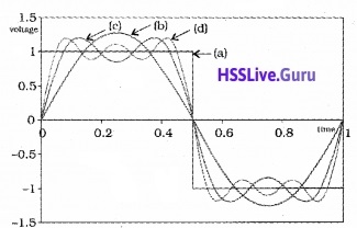
A rectangular wave can be decomposed into a superposition of sinusoidal waves of frequencies ν0, 2ν0, 3ν0, 4ν0………nν0, where n is an integer extending to infinity.
Plus Two Physics Notes Chapter 15 Communication Systems - 3
To produce a rectangular wave, we need to super impose all the harmonics ν0, 2ν0, 3ν0, ………nν0, which implies that bandwidth required for the transmission of rectangular wave is infinite.

For practical purpose, the higher harmonicas are removed. Thus bandwidth is limited. The removal of higher harmonics dos not effect the shape of rectangular wave. Because the contribution of higher harmonics to rectangular wave form is less.

Plus Two Physics Notes Chapter 15 Communication Systems

Bandwidth Of Transmission Medium
Different types of transmission media offer different bandwidths. The commonly used transmission media are wire, free space and fiber optic cable.

Cable offers a bandwidth of 750MHz Optical fibre offers a bandwidth of 1 THz to 1000 THz (Microwaves to ultraviolet).

Propagation Of Electro Magnetic Waves
When the em wave travels through space, the strength of wave decreases.

1. Ground wave:
It is a mode of propagation in which the ground waves progress along the surface of the earth. As the groundwave passes over the surface of the earth, it is weakened as a result of the energy absorption by the surface.

Due to this loss the ground waves are not suited for very large range communication. The ground wave propagation is effective only in very low frequencies (VLF) 500 KHz to 1500 KHz.

2. Sky waves:
It is that mode of wave propagation in which the radiowaves emitted from the transmitting antenna reach the receiving antenna after reflection in the ionosphere.
Plus Two Physics Notes Chapter 15 Communication Systems - 4

Plus Two Physics Notes Chapter 15 Communication Systems
The UV and other high energy radiations coming from sun are absorbed by air molecules. Due to this absorption, the air molecules get ionized and form an ionized layer of electrons and ions around the earth. The ionosphere extends from a height of nearly 80 Km to 300 km above the earth’s surface.

Explanation for reflection of em wave:
The refractive index of ionosphere decreases as we go into the ionosphere. Therefore an em wave coming from ground undergoes fortotal internal reflection.

Since this phenomenon is a frequency dependent one, there is a critical frequency (ranges from 5 to 10 MHz) above which the wave incident on the ionosphere will not reflect back. Therefore, sky wave propagation is not possible above 10 MHz. This limitation is overcome with satellite communication.

3. Space wave:
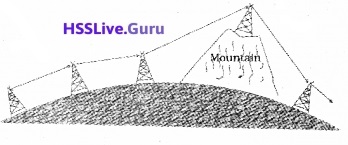
A space wave travels in a straight line from transmitting antenna to the receiving antenna. Space wave communication is also called Line of sight (LOS) communication.
Plus Two Physics Notes Chapter 15 Communication Systems - 5
Because of line-of-sight nature of propagation, direct waves get blocked at some point by the curvature of the earth as illustrated in the above figure.

If the signal is to be received beyond the horizon then the receiving antenna must be high enough to receive the line-of-sight waves.

The maximum line-of-sight distance dM between the two antennas having heights hT and hR above the earth is given by
dm = \(\sqrt{2 R h_{T}}+\sqrt{2 R h_{R}}\)
Note:
At frequencies above 40 MHz, communication is essentially limited to line-of-sight paths. At these frequencies, the antennas are relatively smaller.

Plus Two Physics Notes Chapter 15 Communication Systems

Modulation And Its Necessity
1. Size of the antenna or aerial:
For transmitting and receiving signal we need antenna having a size comparable to the wavelength of the signal (should have length at least one quarter of the wavelength).

Therefore, to transmit a 1 KHz signal it requires about 500m long antenna, which is practically impossible. This demand that the audio signal is to be converted into a high frequency signal fortransmission.

2. Effective power radiated by an antenna:
To send signals to large distances the power of the transmitter should be as high as possible. Transmission power of an antenna is inversely proportional to the square of the wavelength (P α (l/λ)2). Therefore, to attain high radiation power the wavelength should be as small as possible.

3. Mixing up of signals from different transmitters:
Suppose many people are talking at the same time and those audio signals are transmitting simultaneously. All those signals will get mixed up and there is no way to distinguish between them. This problem can be solved by transmitting the audio signals in the form of high frequency signals.

Modulation:
To overcome all those difficulties (mentioned above) we make use of the technique called modulation. Modulation is the process of super posing a low frequency (audio signal) information on to a high frequency carrier wave.

Carrierwave:
The carrierwave may be sinusoidal wave ora pulse train.
Plus Two Physics Notes Chapter 15 Communication Systems - 6

Plus Two Physics Notes Chapter 15 Communication Systems
Sinusoidal carrier wave can be mathematically expressed
c(t) = Ac sin (ωct + Φ)
where c(t)is the signal strength (voltage or current). Ac is the amplitude, ωc (2πvc) is the angular frequency and Φ is the initial phase of the carrier wave.

While modulating, any one of the parameters is varied according to the base band signal (audiosignal). These result in three types of modulation using sinusoidal carrier waves namely

  • Amplitude modulation
  • Frequency modulation
  • Phase modulation

Plus Two Physics Notes Chapter 15 Communication Systems - 7
In a similar way, a pulse train is characterized by pulse amplitude, pulse duration or pulse width and pulse position denoted by the rise and falls of the pulse. Hence different types of pulse modulation are

  • Pulse Amplitude Modulation (PAM)
  • Pulse Width Modulation (PWM)
  • Pulse Position Modulation (PPM)

Plus Two Physics Notes Chapter 15 Communication Systems

Amplitude Modulation
In amplitude modulation the amplitude of the carrier is varied in accordance with the information signal.

Mathematical analysis:
Consider a sinusoidal carrier wave c(t)=Ac sinωct and a modulating signal (message signal) m(t) = Am sinωmt.

The message signal is added in such a way to change the amplitude of carrier wave. Hence the modulated signal can be written as,
cm(t) = (Ac + Am sinωm t) sinωct
= Ac sinωc t + Am sinωm t sinωc t
= Ac sinωc t + µ Ac sinωc t sinωm t
where
Plus Two Physics Notes Chapter 15 Communication Systems - 8
called modulation index.
Using trigonometric relation sinAsinB = 1/2cos(A – B) – cos(A + B) we can write
Plus Two Physics Notes Chapter 15 Communication Systems - 9
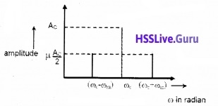
The above equation shows that, the modulated signal consists of three frequencies, ωc, (ωc – ωm), (ωc + ωm) where (ωc – ωm ) is called lower side band frequency and (ωc + ωm) is called upper side band frequency.
A plot of Ac with ω for AM signal:
Plus Two Physics Notes Chapter 15 Communication Systems - 10
Note:
Modulation index (µ) is always kept ≤1 to avoid distortion.

Plus Two Physics Notes Chapter 15 Communication Systems

Production Of Amplitude Modulated Wave
Production of an amplitude-modulated wave is given in a block diagram.
Plus Two Physics Notes Chapter 15 Communication Systems - 11
Step – I:
The modulating signal Amsinωmt is added to the carrier signal Acsinωct to produce x(t).
x(t)=Am sinωm t + Ac sinωc t……..(1)

Step – II:
This signal x(t) = Amsinωmt + Acsinωct is passed through a square law device which is a non-linear device which produces an output.
y(t) = B x(t) + C x(t)2………..(2)
where B and C are constants.
Substitute the eq(1) in eq.(2).
y(t) = B [Am sinωmt + Acsinωct] + C [Am sinωmt + Ac sinωct]2
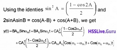
y(t) = B Am sinωmt + B Acsinωc + C [A2m sin2ωm t + A2c sin2ωct + 2AmAc sinωct sinωmt]
Plus Two Physics Notes Chapter 15 Communication Systems - 12

Step – III:
The output from the square law device y(t) is passed to Band pass filter. The Band pass filter remove dc component \(\frac{c}{2}\)(A2m + A2c) and ωm, 2ωm, and 2ωc from the signal y(t).

Hence the output of band bass filter will be amplitude modulated wave containing three frequencies ωc, (ωc – ωm) and (ωc + ωm). ie. Output of band pass filter
= BAωc sinωc t + C AmAc (cos(ωc – ωm )t) + AmAc(cos(ωc + ωm)t)
The output contain three frequencies ωc, (ωc – ωm) and (ωc + ωm).

Transmission of AM wave:
Plus Two Physics Notes Chapter 15 Communication Systems - 13
The AM is given to a power amplifier. The power amplifier provides the necessary power and then the modulated signal is fed to an antenna for radiation.

Plus Two Physics Notes Chapter 15 Communication Systems

Detection Of Amplitude Modulated Wave
The block diagram of AM receiver is shown in figure.
Plus Two Physics Notes Chapter 15 Communication Systems - 14

Step I:
The AM wave is received by the Receiving antenna.

Step II:
The signal from the antenna is given to the amplifier. The amplifier will give sufficient strength to the receiving signal.

Step III:
The output from the amplifier is given to the IF (intermediate frequency) stage. In IF stage, the carrier frequency is changed into a lower frequency.

Step IV:
Detection:
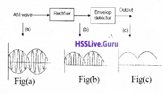
The output from the IF stage is given to the detector. Detection is the process of recovering the modulating signal from the modulated carrier wave. The process of detection is shown in block diagram.

The modulated signal fig (a) is given to the rectifier. The rectifier removes the negative part of the A.M and gives the output as shown in figure (b). This output is given to the envelop detector. The envelop detector gives an output of message signal as shown in figure (c).

Plus Two Physics Notes Chapter 15 Communication Systems

Step V:
The message signal from the detector is given to the amplifier. The amplifier, amplifies the signal and given to the loud speaker.
Plus Two Physics Notes Chapter 15 Communication Systems - 15

Plus Two Physics Notes Chapter 14 Semiconductor Electronics: Materials, Devices and Simple Circuits

Students can Download Chapter 14 Semiconductor Electronics: Materials, Devices and Simple Circuits Notes, Plus Two Physics Notes helps you to revise the complete Kerala State Syllabus and score more marks in your examinations.

Kerala Plus Two Physics Notes Chapter 14 Semiconductor Electronics: Materials, Devices and Simple Circuits

Introduction
Before the discovery of transistor, vacuum tube or valves were considered as the building blocks of electronic circuit.

1. A Comparison of Vacuum Tubes and Transistors:

Vacuum Tubes/valvesTransistors
1. External heating is required. (Electrons are supplied by heated cathode)No external heating is required.
2. Large evacuated space (vacuum) is required be­ tween cathode and anodeEvacuated space is not required
3. The electrons from heated cathode flows through vacuum.The charge carriers flows within solid itself.
4. Bulky (large in size)Small in size
5. Consume high powerLow power consumption
6. Operate at high voltageOperate at low voltage
7. Limited life arid low reliability.Long life and high reliability.

Plus Two Physics Notes Chapter 14 Semiconductor Electronics: Materials, Devices and Simple Circuits

Classification Of Metals, Conductors, And Semiconductors
1. On the basis of conductivity:
On the basis of relative values of electrical conductivity (σ) and resistivity ρ = \(\frac{1}{\sigma}\) solids are classified as

(i) Metals:
They possess very low resistivity (or high conductivity).
ρ → 10-2 – 10-8 Ω m
σ → 102 – 108 S m-1

(ii) Semiconductor:
They have resistivity or conductivity intermediate to metals and insulators.
ρ → 10-5 – 106 Ω m
σ → 105 – 10-6 S m-1

(iii) Insulators: They have high resistivity (or low conductivity).
ρ → 1011 – 1019 Ω m
σ → 10-11 – 10-19 S m-1

2. Band Theory: Conduction Band, Valence Band, and Energy Gap:
In an isolated atom, electrons will have definite energy level. When atoms combine to form solid, the energy levels of outer electrons overlap. Hence outer energy levels split in to many energy levels.

These energy levels are very closely spaced Hence it appears as continuous variation of energy. This collection of energy levels are called energy band.

The energy band which includes energy levels of valence electrons is called valence band. The energy band above valence band which includes energy levels of conduction electrons is called conduction band.

The gap between the top of valence band and bottom of conduction band is called energy band gap (Energy gap, Eg).
Energy level diagram of different bands:
Plus Two Physics Notes Chapter 14 Semiconductor Electronics Materials, Devices and Simple Circuits - 1

Plus Two Physics Notes Chapter 14 Semiconductor Electronics: Materials, Devices and Simple Circuits
The band gap energy of Ge and Si are 0.3ev and 0.7ev respectively.

3. Classification on the basis of Energy bands Conductors:
Conduction band is partially filled and valence band is partially empty.

OR

Conduction band and valence band are overlapped so that Eg = 0ev
Plus Two Physics Notes Chapter 14 Semiconductor Electronics Materials, Devices and Simple Circuits - 2
Due to overlapping, electrons are partially filled in conduction band. These partially filled electrons are responsible for current conduction.

Insulators:
Plus Two Physics Notes Chapter 14 Semiconductor Electronics Materials, Devices and Simple Circuits - 3
Conduction band is empty. Valence band may fully or partially filled. There is a wide energy gap between valence band and conduction band (Eg > 3ev).

Semiconductors:
Conduction band may be empty or lightly filled. Valence band is fully filled. The energy gap is very small (< 3ev)
Plus Two Physics Notes Chapter 14 Semiconductor Electronics Materials, Devices and Simple Circuits - 4
At room temperature some electrons in valence band get enough energy to cross the energy gap and move into conduction. Hence semiconductors show intermediate conductivity.

Plus Two Physics Notes Chapter 14 Semiconductor Electronics: Materials, Devices and Simple Circuits

Intrinsic Semiconductor
A semiconductor in its pure form is called intrinsic semiconductor.

For intrinsic semiconductor:
* The number of free electrons is equal to number of holes.
ie. ne = nh = ni
ne, nh and ni are the free electron concentration, hole concentration and intrinsic carrier concentration.

Explanation:
Each Si atom is covalently bonded to nearest four neighboring atoms. When temperature increase, some of covalent bond brakes and electrons become free leaving a vacancy (hole). Thus each free electron creates hole in the lattice. Hence number of free electrons equals number of holes.

* The total current in intrinsic semi conductor is the sum of free electron current Ie and hole current Ih.
I = Ie + Ih

Explanation:
When an electric field is applied, free electrons move towards positive potential and give rise to electron current, le. The holes move towards negative potential and give rise to hole current. Thus total current is contributed by both free electrons and holes.

Plus Two Physics Notes Chapter 14 Semiconductor Electronics: Materials, Devices and Simple Circuits

Extrinsic Semiconductor
1. Extrinsic semiconductor or impurity semiconductor:
The addition of suitable impurity improves the conductivity of intrinsic semiconductors. Such semiconductors are called extrinsic semiconductor. They are of two types n-type and p-type semiconductors.

2. Doping and Dopants:
The deliberate addition of suitable impurity to semiconductors to improve its conductivity is called doping.
The impurity atoms are called dopants. There are two types of dopants;

  • Pentavalent (valency 5): Arsenic (As), Antimony (Sb), Bismuth (Bi), Phosphorous (P), etc.
  • Trivalent (Valency 3): Indium (In), Boron (B), Aluminium (Al), etc.

3. n-type semiconductor:
When a pentavalent impurity is added to Si crystal, four electrons of impurity atom make bond with neighboring four Si atoms. The fifth electron remains weakly bound to its parent atom.

At room temperature this electron become free to move. Thus each pentavalent atom donate one extra electron for conduction and hence it is called donor impurity.
Plus Two Physics Notes Chapter 14 Semiconductor Electronics Materials, Devices and Simple Circuits - 5
Thus in doped semiconductor the number of conduction electrons will be large compared to number of holes. Hence electrons are the majority carriers and holes the minority carriers. Hence semiconductors doped with pentavalent impurity is called n-type semiconductor.
Note:
In n-type semiconductors
ne >> nh
But as a whole n-type semiconductor is neutral (ie. electrons is equal and opposite to ionized (donor) core in lattice).

4. p-type semiconductor:
When a trivalent impurity is added to Si crystal, three electrons of impurity atom make covalent bond with neighboring three Si atom. The fourth bond with neighboring Si atom lacks one electron. Thus a vacancy or a hole is created in fourth bond.

Plus Two Physics Notes Chapter 14 Semiconductor Electronics: Materials, Devices and Simple Circuits

The neighboring Si atom needs an electron to fill the vacancy and hence one electron in outer orbit of nearby Si atom move to this vacancy leaving a hole in its own site. Thus hole can move through the lattice.

Each trivalent atom creates a hole and it act as acceptor. Hence it is called acceptor impurity. The semiconductor doped with trivalent impurity has more number of holes than free electrons. Here holes are the majority carriers and electrons are the minority carriers. Hence it is called p-type semiconductor.
Note: I
(I) In p-type semi conductor
nh >> ne
But as a whole p-type semiconductor is electrically neutral. (The charge of additional holes is equal and opposite to acceptor ions).

(II) In thermal equilibrium electron and hole concentration in a semiconductor is given by nenh = n2r.

5. Energy band structure of Extrinsic semiconductors
n-type semiconductor:
Plus Two Physics Notes Chapter 14 Semiconductor Electronics Materials, Devices and Simple Circuits - 6
In n-type semiconductors, the donor energy level (ED) is slightly below conduction band.

P-type semiconductor:
Plus Two Physics Notes Chapter 14 Semiconductor Electronics Materials, Devices and Simple Circuits - 7
In p-type semiconductors, the acceptor energy level (EA) lies slightly above valence bond.

Plus Two Physics Notes Chapter 14 Semiconductor Electronics: Materials, Devices and Simple Circuits

p-n Junction
A p-n junction is basic building block of semiconductor devices like diode, transistor, etc.

1. p-n junction formation:
When pentavalent impurity is added to a part of p-type Si semiconductor wafer, we get both p region and n region in a single wafer.
The formation of p-n junction includes two processes.

(i) Diffusion:
In n type semiconductor, concentration of electrons is more than that of holes. In p-region, the hole concentration is more than electron concentration. Because of this concentration gradient, electrons diffuse from n side to p-side and holes diffuse from p-side to n-side during the formation of p-n junction. This produces diffusion current.

(ii) Drifting – Formation of Depletion region:
Plus Two Physics Notes Chapter 14 Semiconductor Electronics Materials, Devices and Simple Circuits - 8
When electrons diffuses from n to p, it leaves behind positively charged immobile donor ions on n-side. As electrons continue to diffuse from n to p, a layer of positive charge is developed on n- side.

Similarly when holes diffuse from p to n, it leaves behind negatively charged immobile ions on p side. As holes continue to diffuse from p to n, negative space charge region is developed on p side.

The positive space-charge region on n-side and negative space-charge region on p-side, is known as depletion region. This region contain only immobile ions.

2. Barrier Potential:
The n-region losses electrons and p-region gains electrons. Because of this a potential is developed across the junction. This potential is called barrier potential.

Plus Two Physics Notes Chapter 14 Semiconductor Electronics: Materials, Devices and Simple Circuits

Semiconductor Diodes
A semiconductor diode is a p-n junction provided with metallic contact at both ends to apply external voltage.
The symbol of p-n junction diode is given below.
Plus Two Physics Notes Chapter 14 Semiconductor Electronics Materials, Devices and Simple Circuits - 9
The arrow shows conventional direction of current.

1. p-n junction diode under forward bias:
When p-side of p-n junction diode is connected to positive terminal of the battery and n-side to the negative terminal it is said to be in forward biased.
Plus Two Physics Notes Chapter 14 Semiconductor Electronics Materials, Devices and Simple Circuits - 10
Due to the applied voltage, electrons of n-side get repelled by negative terminal of battery. Hence they cross depletion region and reach at p-side.

similarly the holes of p-side get repelled by positive terminal of battery and cross depletion region, reach n-side. The total forward current is sum of hole current and current due to electron.

2. p-n junction diode under reverse bias:
When p-side of p-n junction diode is connected to negative terminal of battery and n-side to the positive terminal, it is said to be in reversed biased.
Plus Two Physics Notes Chapter 14 Semiconductor Electronics Materials, Devices and Simple Circuits - 11

Plus Two Physics Notes Chapter 14 Semiconductor Electronics: Materials, Devices and Simple Circuits
In reverse bias the electrons of n-side and holes on p-side cannot cross the junction. But the minority carriers – holes on n-side and electrons on p-side drift across the junction and produce current. The reverse current is of the order micro ampere.
Note: Junction width increases in reverse bias.

Breakdown Voltage (VBr):
The reverse current remains independent of bias voltage up to a critical reverse bias voltage called reverse break down voltage. At breakdown voltage, reverse current increases sharply.

V-I characteristics:
To study variation of current with voltage for p-n junction diode, it is connected to a battery through a rheostat. Rheostat is used to vary the biasing voltage. A milliammeter is connected in series with diode to study forward current.

To measure reverse current micro ammeter is used. A voltmeter is connected across diode to measure voltage. The current is measured for different values of volt and a graph (V-I) is plotted.
Plus Two Physics Notes Chapter 14 Semiconductor Electronics Materials, Devices and Simple Circuits - 12
In forward bias, current first increases very slowly up to a certain value of bias voltage. After this voltage, diode current increases rapidly. This voltage is called Knee voltage or cut-in voltage or threshold voltage. (0.2v for Ge and 0.7v for Si). The diode offers low resistance in forward bias.

In reverse bias, current is very small. It remains almost constant up to break down voltage (called reverse saturation current). Afterthis voltage reverse current increases sharply.
Note:
(i) In forward bias, resistance is low compared to reverse bias.
(ii) The dynamic resistance of diode is defined as ratio of change in voltage to change in current.
rd = \(\frac{\Delta v}{\Delta l}\)

Plus Two Physics Notes Chapter 14 Semiconductor Electronics: Materials, Devices and Simple Circuits

Application Of Junction Diode
Diode as a rectifier:
The process of converting AC into DC is known as Rectification. A p-n junction diode conducts current when it is forward biased, and does not conduct when it is reverse biased. This feature of the junction diode enables it to be used as rectifier.

1. Diode as half wave rectifier:
Plus Two Physics Notes Chapter 14 Semiconductor Electronics Materials, Devices and Simple Circuits - 13
Circuit details:
A half wave rectifier consists of transformer, a diode and a load resistor RL. The primary coil of transformer is connected to a.c input and secondary is connected to RL through diode.

Working:
During the positive half cycle of the input a.c at secondary, the diode is forward biased and hence it conducts through RL. During negative half cycle of a.c at secondary, diode is reverse biased and does not conduct. Thus, we get +ve half cycle at the output. Hence the a.c input is converted into d.c output.

2. Full wave rectifier:
Circuit details:
Plus Two Physics Notes Chapter 14 Semiconductor Electronics Materials, Devices and Simple Circuits - 14
Full wave rectifier consists of transformer, two diodes, and a load resistance RL. Input a.c signal is applied across the primary of the transformer. Secondary of the transformer is connected to D1 and D2. The output is taken across RL.

Working:
During the +ve half cycle of the a.c signal at secondary, the diode D1 is forward biased and D2 is reverse biased. So that current flows through D1 and RL.

During the negative half cycle of the a.c signal at secondary, the diode D1 is reverse biased and D2 is forward biased. So that current flows through D2 and RL.

Thus during both the half cycles, the current flows through RL in the same direction. Thus we get a +ve voltage across RL for +ve and -ve input. This process is called full wave rectification.

Plus Two Physics Notes Chapter 14 Semiconductor Electronics: Materials, Devices and Simple Circuits

Special Purpose p-n Junction Diodes
1. Zener diode:
Zener diode is designed to operate under reverse bias in the breakdown region. It is used as a voltage regulator. The symbol for Zener diode is shown in figure.
Plus Two Physics Notes Chapter 14 Semiconductor Electronics Materials, Devices and Simple Circuits - 15
Zener diode is heavily dopped. Hence depletion region is very thin.
I-V characteristics of zener diode:
Plus Two Physics Notes Chapter 14 Semiconductor Electronics Materials, Devices and Simple Circuits - 16
The l-V characteristics of a Zener diode is shown in above figure. At break down voltage, current increases rapidly. After breakdown, zener voltage remains constant. This property of the Zenerdiode is used for regulating supply voltages.

Explanation for large reverse current:
Reverse current is due to the flow of electrons (minority carriers) from p to n and holes from n to p. When the reverse bias voltage increases and becomes V = V2 high electric field is developed. This high electric field can pull valence electrons from the atoms. These electrons account for high current.

1. (a) Zener diode as avoltage regulator Principle:
In reverse breakdown region, the voltage across the diode remains constant.
Circuit details:
Plus Two Physics Notes Chapter 14 Semiconductor Electronics Materials, Devices and Simple Circuits - 17

Plus Two Physics Notes Chapter 14 Semiconductor Electronics: Materials, Devices and Simple Circuits
The zenerdiode is connected to a fluctuating voltage supply through a resistor Rz. The out put is taken across RL.

Working:
When ever the supply voltage increases beyond the breakdown voltage ,the current through zener increases (and also through Rz).

Thus the voltage across Rz increases, by keeping the voltage drop across zenerdiode as a constant value. (This voltage drop across Rz is proportional to the input voltage).

2. Optoelectronic junction devices:
(i) Photodiode:
The photodiode can be used as a photodetector to detect optical signals.
Plus Two Physics Notes Chapter 14 Semiconductor Electronics Materials, Devices and Simple Circuits - 18
It is operated under reverse bias. When the photodiode is illuminated with light (photons) electron-hole pairs are generated. Due to electric field of the junction, electrons and holes are separated before they recombine.

The direction of the electric field is such that electrons reach n-side and holes reach p-side. Electrons collected on n-side and holes collected on p- side produce an emf. When an external load is connected, the current flows through the load.
The I-V characteristics of a photodiode:
Plus Two Physics Notes Chapter 14 Semiconductor Electronics Materials, Devices and Simple Circuits - 19

Plus Two Physics Notes Chapter 14 Semiconductor Electronics: Materials, Devices and Simple Circuits

(ii) Light emitting diode [LED]:
LED is heavily doped pn junction diode working under forward bias .Gallium Arsenide is used for making infrared LEDs.

Working:
When the junction diode is forward biased, electrons and holes flow in opposite directions across junction. Some of the electrons and holes combine at junction and energy is produced in the form of light.

Uses:
LEDs are used in remote controls, burglar alarm systems, optical communication, etc.

Advantages of LED over conventional incandescent lamps:

  1. Low operational voltage and less power.
  2. Fast action and no warm-up time required.
  3. The bandwidth of emitted light is 100 A° to 500 A° or in other words it is nearly (but not exactly) monochromatic.
  4. Long life and ruggedness.
  5. Fast on-off switching capability.

3. Solar cell:
Solar cell is junction diode used to convert solar energy into electrical energy.
Circuit details:
Plus Two Physics Notes Chapter 14 Semiconductor Electronics Materials, Devices and Simple Circuits - 20
Its p-region is thin and transparent and is called emitter. The n-region is thick and is called base. Output is taken across RL.

Working:
When light falls on this layer, electrons from the n-region cross to the p-region and holes in the p-region cross in to the n-region. Thus a voltage is developed across RL. Solar cells are used to charge storage batteries during daytime.
The I-V characteristics of a solar cell:
Plus Two Physics Notes Chapter 14 Semiconductor Electronics Materials, Devices and Simple Circuits - 21
The I-V characteristics of solar cell is drawn in the fourth quadrant of the coordinate axes. This is because a solar cell does not draw current but supplies the same to the load.

Plus Two Physics Notes Chapter 14 Semiconductor Electronics: Materials, Devices and Simple Circuits

Junction Transistor
1. Transistor: structure and action
Transistor is a three layered doped semiconductor device. There are two types of transistors:

  • n-p-n transistor
  • p-n-p transistor.

Plus Two Physics Notes Chapter 14 Semiconductor Electronics Materials, Devices and Simple Circuits - 22
Symbols:
Plus Two Physics Notes Chapter 14 Semiconductor Electronics Materials, Devices and Simple Circuits - 23
Naming the transistor terminals:
A transistor has 3 terminals:

  1. Emitter
  2. Collector
  3. Base.

1. Emitter:
The section, which supplies charge carriers, is called emitter. Emitter is heavily doped. The emitter should be forward biased.

2. Collector:
The section which collects the charge carriers, is called collector. Collector is moderately doped. The collector should be reverse biased.

3. Base:
Middle section between emitter and ‘ collector is called base. Base is lightly doped.

Transistor action:
Circuit details:
Emitter is maintained at forward bias and collector is maintained at reverse bias. VEB is the emitter base voltage and VCB is the collector base voltage.
Plus Two Physics Notes Chapter 14 Semiconductor Electronics Materials, Devices and Simple Circuits - 24

Plus Two Physics Notes Chapter 14 Semiconductor Electronics: Materials, Devices and Simple Circuits

Working:
Emitter is kept at forward bias so that the electrons are ejected into base. Thus an emitter current IE is produced.

At the base, electron hole combination takes place. As the base is lightly doped and very thin, only a few electrons combine with holes to constitute the base current, IB.

The remaining electrons are attracted towards collector because the collector is kept at reverse bias. Due to this electron flow, a collector current IC is produced.

In this way, the emitter current is divided into base current and collector current.
Mathematically this can be written as
IE = IB + IC
IB > is small, so IE = IC

2. Basic transistor circuit configurations and transistor characteristics:
Transistor can be used in three modes:

  • Common base configuration
  • Common emitter configuration
  • Common collector configuration

a. Common base configuration:
Plus Two Physics Notes Chapter 14 Semiconductor Electronics Materials, Devices and Simple Circuits - 25
In Common base configuration .base is common to both input and output
Current amplification = \(\frac{\text { output current }}{\text { input current }}\)
Current amplification, α = \(\frac{l_{C}}{l_{E}}\)

b. Common emitter configuration:
Plus Two Physics Notes Chapter 14 Semiconductor Electronics Materials, Devices and Simple Circuits - 26
Current amplification = \(\frac{\text { output current }}{\text { input current }}\)
Current amplification, β = \(\frac{l_{C}}{l_{B}}\)

c. Common collector configuration:
Current amplification γ = \(\frac{l_{E}}{l_{B}}\)

Relation between α and β:
i.e. β = \(\frac{\alpha}{I-\alpha}\)
Common Emitter Configuration:
Plus Two Physics Notes Chapter 14 Semiconductor Electronics Materials, Devices and Simple Circuits - 27

Plus Two Physics Notes Chapter 14 Semiconductor Electronics: Materials, Devices and Simple Circuits
Input Characteristics (CE configuration):
The graph connecting base current with base emitter voltage (at constant VCE) is the input characteristics of the transistor.
Plus Two Physics Notes Chapter 14 Semiconductor Electronics Materials, Devices and Simple Circuits - 28
To study the input characteristics, the collector to emitter voltage (VCE) is kept at constant. The base current IB against VBE is plotted in a graph.
The ratio ∆ VBE/∆ IB at constant VCE is called the input resistance.
i.e,,Input resistance \(r_{1}=\frac{\Delta V_{B E}}{\Delta I_{B}}\)

Output Characteristics (CE. Configuration):
The output characteristics is a graph connecting the collector current lc with collector-emitter voltage (VCE) at a constant base current (IB).
Plus Two Physics Notes Chapter 14 Semiconductor Electronics Materials, Devices and Simple Circuits - 29
This is obtained by measuring the collector current IB at different collector voltage by keeping the base current fixed.

Line OA is called saturation line .The region right of the saturation line is the active region. Transistor is operated as amplifier in this region. The region below IB = 0 is the cut off region.

The output resistance is the ratio of a small change in collector voltage to the change in collector current at constant base current.
Output resistance \(\mathrm{r}_{0}=\frac{\Delta \mathrm{V}_{\mathrm{CE}}}{\Delta \mathrm{I}_{\mathrm{C}}}\)

3. Transistor as a device
Transistor as a switch:
A circuit diagram for transistor switch is given below.
Plus Two Physics Notes Chapter 14 Semiconductor Electronics Materials, Devices and Simple Circuits - 30
Applying Kirchoff’s voltage rule to the input side of this circuit, we get
VBB = IBRB + VBE
and applying Kirchoff’s voltage rule to the output side of this circuit, we get
VCE = VCC – ICRC.
We shall treat VBB as the dc input voltage Vi and VCE as the dc output voltage Vo.
So, we have
Vi = IBRB + VBE ____(1) and
Vo = VCC – ICRi______(2)

The variation of output voltage with input voltage:
Plus Two Physics Notes Chapter 14 Semiconductor Electronics Materials, Devices and Simple Circuits - 31
The variation of output voltage with input voltage is shown in the above graph. This graph contain three regions

  • cut off region
  • Active region
  • saturation region.

Plus Two Physics Notes Chapter 14 Semiconductor Electronics: Materials, Devices and Simple Circuits

a. Cut off region:
In the case of Si transistor, if input voltage Vi is less than 0.6V, the transistor will be in cut off state and out put current (Ic) will be zero.
Substituting Ic = 0 in the eq (2) we get out put voltage Vo = VCC

b. Active region:
When Vi becomes greater than 0.6 V the transistor is in active state with some current Ic. The eq(2) shows that, the output Vo decrease as the term IcRc increases. With increase of Vi, Ic increases almost linearly and so Vo decreases linearly till its value becomes less than about 1.0 V.
Note:
Amplifier is working in the active region.

c. saturation region:
When the output voltage becomes 1.0V, the change becomes non linear and transistor goes into saturation state. With further increase in Vi the output voltage is found to decrease towards zero (though it may never become zero).

Working of transistor as switch:
When Vi is low (unable to give forward-bias to the transistor) we get high output (ie. Vo = Vcc). In this stage the transistor doesn’t conduct. Hence transistor is said to be switched off.

If Vi is high enough to drive the transistor into saturation, then Vo is low (very near to zero). In this stage the transistor driven into saturation it is said to be switched on.
Note:
The switching circuits are designed in such a way that the transistor does not remain in active state.

4. Transistoras an Amplifier (CE-Configuration):
Plus Two Physics Notes Chapter 14 Semiconductor Electronics Materials, Devices and Simple Circuits - 32
The working of an amplifier can be explained using the circuit given above. It is an n-p-n transistor connected in common emitter configuration. VBB is the biasing voltage used in the input side and Vcc is the reverse bias voltage used in the output side.

RB is the resistor connected to base in order to reduce the base current. Rc is the resistor which is connected in between Vcc and collector terminal. We take the voltage across Rc and Vcc with the help of a capacitor C. We maintain voltages VBB and Vcc such that the transistor is always on the active region.

Plus Two Physics Notes Chapter 14 Semiconductor Electronics: Materials, Devices and Simple Circuits

Working:
Case 1:
When there is no input signal (ie. Vi = 0,)
The input voltage can be written as
VBB = VBE + IBRB
This base voltage produces a base current IB which in turn produces a dc collector current IC. The output voltage can be written as
VCE = VCC – ICRC
This dc output voltage is unable to produce an output signal due to the presence of a capacitor. Because, the capacitor prevents the flow of dc current through it.

Case 2:
When there is an input ac signal, (ie. Vi ≠ 0):
when we apply an AC signal as input, we get an AC base current denoted by iB. Hence input AC voltage can be written as
Vi = iBr ______(1)
where ‘r’ is the effective input resistance.
This AC input current produces an AC output current (ic) which can flow through a capacitor. Hence the output voltage can be written as
V0 = ic × output resistance
If we take output resistance as RL then vo becomes
V0 = ic RL
V0 = βAC ic × RL _____(2) [since βAC = \(\frac{\mathrm{i}_{\mathrm{C}}}{\mathrm{i}_{\mathrm{B}}}\)]
Plus Two Physics Notes Chapter 14 Semiconductor Electronics Materials, Devices and Simple Circuits - 33

Power gain:
The power gain Apcan be expressed as the product of the current gain and voltage gain.
ie. power gain Aρ = βac × Av
Note:
The transistor is not a power generating device. The energy for the higher ac power at the output is supplied by the battery.

5. Feedback amplifier and transistor oscillator 9.13 Oscillator:
Atransistor amplifier can be converted in to oscillator by positive feed back, (positive feed back means that, a small portion of the out put signal is applied to the input in phase).

Circuit Details:
The battery Vcc is connected in between C (collector) and E (emitter) through a coil L1. Another coil Lis connected in between B (base) and E. A capacitor is connected in parallel to coil L.

Working:
Plus Two Physics Notes Chapter 14 Semiconductor Electronics Materials, Devices and Simple Circuits - 34
Plus Two Physics Notes Chapter 14 Semiconductor Electronics Materials, Devices and Simple Circuits - 35
When the key is pressed ,a small current flows through the coil L11. The variation of current in the coil L1 produces a change in flux. This change in flux induces a voltage across L.

As a result, the forward voltage increases which further increases the emitter and collector current. This again increases the forward voltage. This process continues till the collector gets saturated.

When the collector current is saturated (constant), the flux also become steady and the induced emf becomes zero. This reduces collector current. The decrease in collector current induces a voltage in L in the opposite direction (reverse voltage). As a result the collector current decreases further.

This continues until the collector current falls below its normal value. After this, the collector current build up and the process is repeated. Thus oscillation of frequency.
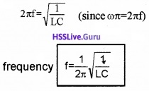
f = \(\frac{1}{2 \pi \sqrt{L C}}\) is produced.

Plus Two Physics Notes Chapter 14 Semiconductor Electronics: Materials, Devices and Simple Circuits

Digital Electronics And Logic Gates
In digital electronics we use two levels of voltage (represented by 0 and 1). Such signals are called digital signals. Logic gates are the building blocks of digital circuits. Logic gates are used in calculators, digital watches, computers, robots, industrial control systems, and in telecommunication.

1. Logic gates:
A logic gate is a digital circuit that follows certain logical relationship between input and output voltage. Hence it is so called. The funda¬mental logic gates are AND, OR, NOT, NAND, and NOR. The truth table gives all possible input logic level combinations with their respective output logic levels.

(i) NOT gate:
The most basic gate which has only a single input and single output. It is also called inverter. It produces an inverted version of input. The Boolean expression is y = \(\overline{\mathrm{A}}\)
The symbol is
Plus Two Physics Notes Chapter 14 Semiconductor Electronics Materials, Devices and Simple Circuits - 36
A The truth table is

InputOutput
AY
10
01

(ii) OR gate:
It has two or more inputs but a single output. The output is high when either inputs or both inputs are high.
The Boolean expression is Y = A + B (read as A or B)
The symbol is
Plus Two Physics Notes Chapter 14 Semiconductor Electronics Materials, Devices and Simple Circuits - 37
The truth table:
Plus Two Physics Notes Chapter 14 Semiconductor Electronics Materials, Devices and Simple Circuits - 38

Plus Two Physics Notes Chapter 14 Semiconductor Electronics: Materials, Devices and Simple Circuits

(iii) AND gate:
It has two or more inputs but a single output. The output is high only if both inputs are high. The Boolean express of output is Y = A.B (read as A and B)
The symbol is
Plus Two Physics Notes Chapter 14 Semiconductor Electronics Materials, Devices and Simple Circuits - 39
The truth table
Plus Two Physics Notes Chapter 14 Semiconductor Electronics Materials, Devices and Simple Circuits - 40

(iv) NAND gate (or bubbled AND gate):
This is an AND gate followed by NOT gate. The Boolean expression is y = \(\overline{\mathrm{A.B}}\)
The symbol is
Plus Two Physics Notes Chapter 14 Semiconductor Electronics Materials, Devices and Simple Circuits - 41
The truth table
Plus Two Physics Notes Chapter 14 Semiconductor Electronics Materials, Devices and Simple Circuits - 42

(v) NOR gate (or bubbled OR gate):
It has two or more inputs and one output. This is OR gate followed by NOT gate.
The Boolean expression is Y = \(\overline{A+B}\)
The symbol is
Plus Two Physics Notes Chapter 14 Semiconductor Electronics Materials, Devices and Simple Circuits - 43
The truth table is
Plus Two Physics Notes Chapter 14 Semiconductor Electronics Materials, Devices and Simple Circuits - 44
NAND gate and NOR gate are called universal gates because other basic gates like OR, AND and NOT gate can be realized using them.

Plus Two Physics Notes Chapter 14 Semiconductor Electronics: Materials, Devices and Simple Circuits

Integrated Circuits
The entire circuit fabricated on a small piece of semiconductor or chip is called Integrated Circuit (IC). It contain many transistors, diodes, resistors, capacitors, connecting wires – all in one package.

It was invented by Jack Kilky in 1958 and won Nobel prize for this invention. IC’s are produced by a process called photolithography. IC’s are categorized depending on nature of input signals.

(a) Linear or analogue IC:
These IC’s handle analogue signals and output varies linearly with input.
Eg: Operational Amplifier

(b) The digital IC:
These type handles digital signals and mainly contain logic gates Depending on the level of integration (number of circuit components or logic gates), IC are classified as

  • SSI – Small scale Integration (logic gates ≤ 10)
  • MSI – Medium Scale Integration (logic gates ≤ 100))
  • LSI – Large scale Integration (logic gates ≤ 1000)
  • VLSI – Very Large scale integration (logic gates > 1000)

The miniaturization in electronics technology is brought about by the Integrated circuit. It has made the things faster and smaller. IC is the heart of computer system. In fact IC’s are found in almost all electrical devices like cars, televisions, CD players, cell phones, etc.

Plus Two Physics Notes Chapter 13 Nuclei

Students can Download Chapter 13 Nuclei Notes, Plus Two Physics Notes helps you to revise the complete Kerala State Syllabus and score more marks in your examinations.

Kerala Plus Two Physics Notes Chapter 13 Nuclei

Introduction
In this chapter, We shall discuss various properties of nuclei such as their size, mass and stability, and also associated nuclear phenomena such as radioactivity, fission and fusion.

Atomic Masses And Composition Of Nucleus
1. Atomic Mass Unit (amu or u):
The most commonly used unit to express atomic mass of nucleus is atomic mass unit (u). It is defined as 1/12th of mass of carbon atom (C12).
Plus Two Physics Notes Chapter 13 Nuclei - 1

Plus Two Physics Notes Chapter 13 Nuclei

2. Proton:
The nucleus of lightest atom (isotope) of hydrogen is called proton. The mass of proton is
mp = 1.00727u = 1.67262 × 10⁻²⁷ kg
The charge of proton is +1.6 × 10⁻¹⁹ and it is stable.

3. Discovery of Neutron:
Neutron was discovered by James Chadwick. He bombarded Beryllium nuclei with α particles and observed the emission of neutral radiation. He assumed the neutral radiation consists of neutral particles called neutron.

4. Neutron:
Neutron is changeless particle of mass 1.6749 × 10⁻²⁷kg. Neutron is stable inside nucleus but it is unstable in its free state.

5. Representation of Nuclide:
Nuclear species or nuclides are represented by notation AZX, where X is the chemical symbol of species.
Z → Atomic Number = Number of protons (electrons)
N → Neutron Number = Number of neutrons
A → Mass Number = Z + N (Total number of protons and neutrons)

6. Isotopes, Isobars and Isotones:
Plus Two Physics Notes Chapter 13 Nuclei - 2

Size Of The Nucleus
The radius of nucleus is related to mass number (A) by the equation
R = R0A1/3
where 0 = 1.2 × 10⁻¹⁵ m
The volume of nucleus (the shape of nucleus is assumed to be spherical) is proportional to A.
ie. Volume = \(\frac{4}{3}\)πR3 = \(\frac{4}{3}\)R03.A
∴ Volume α A
The density of nucleus is constant. It is independent of A and its value is 2.3 × 10¹⁷kgm-3

Plus Two Physics Notes Chapter 13 Nuclei

Mass Energy And Nuclear Binding Energy
1. Mass Energy:
According to Einstein mass is considered as a source of energy. The mass ‘m’ can be converted into energy according to relation
E = mc2
This is mass energy equivalence relation. C is the velocity of light (3 × 10⁸m/s).

2. Nuclear binding energy:
(A) Mass Defect:
The mass defect (Am) is the difference in the mass of nucleus and total mass of constituent nucleons.
∆m = (ZMP + (A – Z)mn] – M
mP and mn are mass of proton and neutron respectively. M is the mass of nucleus.
Eg: In 168O, there are 8 protons and 8 neutrons. The atomic mass of 118O is 15.99493u. The expected mass of 168O is sum of masses of its nucleons.
Total mass of nucleons
= 8 × mP + 8 × mn
= 8 × 1.00727u + 8 × 1.00866u
= 16.12744u
The difference in mass,
∆m = 16.12744u – 15.99493u = 0.13691u

(B) Binding Energy and Binding Energy per nucleon (Eb and Ebn):
Binding Energy: Mass defect (∆m) gets converted into energy as
Eb = ∆mc2
This energy is called binding energy. Which binds nucleons inside the nucleus.

Binding Energy per nucleon:
Binding energy per nucleon Ebn is the ratio of binding energy of nucleus to number of nucleons
Ebn = \(\frac{E_{b}}{A}\)
Ebn is the measure of stability of nucleus.

Plus Two Physics Notes Chapter 13 Nuclei

(C) Plot of Ebn versus mass number, A Main features of the graph:

  • Ebn is almost constant for nuclei whose mass number ranges as 30 < A < 170. The maximum value of Ebn is 8.75Mev for 56Fe and it is 7.6MeV for 238U.
  • Ebn is low for lighter nuclei and also for heavier nuclei.
  • There appear narrow spikes in the curve.

The conclusions from the features of graph:

  • The force is attractive and sufficiently strong.
  • The nuclear force is short range. Each nucleon has its influence on its immediate neighbors only so nuclear force is saturated.
  • Heavier nuclei like U238 have low Ebn. So it split up into nuclei of high Ebn releasing energy ie. it undergoes fission.
  • Lighter nuclei like 2H, 3H, etc. have low Ebn. So it combine to form a heavier nuclei of high Ebn releasing energy ie. it undergoes nuclear fusion.
  • The nuclei at the peaks of narrow spikes have high Ebn which shows extra stability.

Nuclear Force
The features of nuclear force are:

  1. The nuclear force is the strongest force in nature.
  2.  The nuclear force is saturated. It is short range force.
  3. The nuclear force is charge independent ie. nuclear force between proton-proton, neutron-neutron, and proton-neutron are the same.

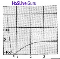
Variation of potential energy with distance:
The potential energy of a pair of nucleons as a function of their separation is shown in the figure
Plus Two Physics Notes Chapter 13 Nuclei - 3
Plus Two Physics Notes Chapter 13 Nuclei - 4
At a particular distance r0, potential energy is minimum. The force is attractive when r > r0 and it is repulsive when r < r0. The value of r0 is about 0.8fm.

Plus Two Physics Notes Chapter 13 Nuclei

Radioactivity
A.H. Becquerel discovered radioactivity.
In radioactive decay, unstable nucleus undergoes decay into stable one. There are three types of decay

  1. α decay
  2. β decay
  3. γ decay

1. Law of Radioactive Decay:
According to Law of Radioactive decay, the number of nuclei undergoing decay per unit time (or rate of decay) is proportional to number of nuclei in the sample at that time.
Plus Two Physics Notes Chapter 13 Nuclei - 5
λ is decay constant or disintegration constant. The negative sign indicates that number of nuclei is decreasing with time. The solution to the above differential equation is
N = N0e-λt
N0 is the initial number of atoms. This equation shows that number of nuclei is decreasing exponentially with time as shown below.
Plus Two Physics Notes Chapter 13 Nuclei - 6
Derivation of equation N(t) = N(0)e-λt
According to Law of Radioactive decay,
\(\frac{d N}{d t}\) = -λn
\(\frac{d N}{d t}\) = -λdt
Integrating
InN = -λt + C_____(1)
C is the constant of integration. To get value of C, let us assume that initially (t = 0) the number of nuclei be N0
∴ C = In N0
Substituting for C in equation (1) we get,
InN – In N0 = -λt
In\(\frac{N}{N_{0}}\) = -λt
\(\frac{N}{N_{0}}\) = e-λt
N = N0e-λt

Plus Two Physics Notes Chapter 13 Nuclei

(A) The decay rate (R):
The decay rate is number of nuclei disintegrating per unit time and is denoted by R.
R = \(\frac{-d N}{d t}\)
Differentiating the equation N = N0e-λt, we get
Plus Two Physics Notes Chapter 13 Nuclei - 7
In terms of decay rate we get R = R0e-λt
where R0 = λN0, decay rate at t = 0

(B) Half life (T1/2):
It is the time taken by radio nuclide to reduce half of its initial value.
half life period T1/2 = \(\frac{0.693}{\lambda}\)
Relation between (T1/2) and λ
If T1/2 is the half-life period, then N = \(\frac{\mathrm{N}_{0}}{2}\)
Substituting these values in N = N0e-λt, we get,
\(\frac{\mathrm{N}_{0}}{2}\) = N0e-λT1/2
2 = e-λT1/2
Taking log on both sides we get,
loge2 = λT1/2 (since log ex = x)
Plus Two Physics Notes Chapter 13 Nuclei - 8

(C) Mean life(t) or average life:
It is defined as time taken by radio nuclei to reduce 1/eth of its initial value.
Mean life τ = \(\frac{1}{\lambda}\)
proof
We know In (\(\frac{N}{N_{0}}\)) = -λt
Plus Two Physics Notes Chapter 13 Nuclei - 9
∴ t = τ, N = \(=\frac{N_{0}}{e}\)
In(1/e) = -λτ
In(e) = λτ
In e = 1
1 = λτ
∴ τ = 1/λ

(D) Relation between τ and T1/2
T1/2 = 693τ

Plus Two Physics Notes Chapter 13 Nuclei

(E) Units of Radioactivity:
The SI unit for radio activity is Becquerel. One becquerel is one disinte¬gration per second. The traditional unit of activity is curie.
1 curie = 3.7 × 10¹⁰ Bq

2. Alpha Decay (α decay):
In α decay, mass number is reduced by 4 units and atomic number is reduced by 2 units.
Plus Two Physics Notes Chapter 13 Nuclei - 10
Q-value
Q value is the energy released in nuclear reaction. The Q value or disintegration energy of a decay can be defined as the difference between the initial mass energy and final mass energy of decay products The Q value of a decay is expressed as
Q = (mx – my – mHe)c2

3. Beta decay (β – decay): There are two types of β decay

  • β+ decay
  • β decay

a. β+ decay:
In β+ decay atomic number is reduced by 1 unit. But mass number remains unchanged.
Plus Two Physics Notes Chapter 13 Nuclei - 11
In β+ decay, positron and neutrino are emitted. In β+ decay, conversion of proton into neutron, positron and neutrino takes place.
Plus Two Physics Notes Chapter 13 Nuclei - 12

b. β decay:
In β decay, atomic number is increased by 1 unit. But mass number does not change.
Plus Two Physics Notes Chapter 13 Nuclei - 13
In β decay a neutron converts into proton emitting electron and antineutrino.
Plus Two Physics Notes Chapter 13 Nuclei - 14

Plus Two Physics Notes Chapter 13 Nuclei

4. Gamma Decay:
The excited nucleus comes back to ground state by emitting gamma rays.
Eg:
Plus Two Physics Notes Chapter 13 Nuclei - 15

5. Properties of α, β and γ:
Properties of α – particle:

  • α -particles have a charge of +2e and a mass four times that of hydrogen atom.
  • They are deflected by electric and magnetic fields.
  • They affect photographic plates.
  • They produce fluorescence and phosphorescence.
  • They have a high ionizing power.
  • They can penetrate very thin metal foils.
  • The velocity is of the order of 107 m/s.

Properties of β – particles:

  • β – particle is an electron.
  • They are deflected by electric and magnetic fields.
  • They can affect photographic plates.
  • They can produce fluorescence and phosphorescence
  • They have low ionization power.

Properties of γ – ray:

  • γ – rays are electromagnetic waves.
  • They have the speed of light.
  • They have high penetrating power.
  • They can affect photographic plates.
  • They can produce fluorescence and phosphorescence.
  • They have ionizing power.
  • They are not deflected by electric and magnetic fields.

Plus Two Physics Notes Chapter 13 Nuclei

Nuclear Energy:
In the nuclear reactions, huge quantity of energy is released

1. Fission:
In nuclear fission, a heavier nuclei split into lighter ones releasing huge energy. When Uranium atom is bombarded with neutron, it breaks into intermediate mass fragments as shown.
Plus Two Physics Notes Chapter 13 Nuclei - 16
Note:

  • The energy released perfission of Uranium nucleus is 200MeV.
  • The neutrons released per fission of Uranium nucleus is 2.5
  • Controlled chain reaction (nuclear fission) is basic principle of nuclear reactor.
  • Uncontrolled chain reaction results in explosion. This is the principle behind atom bomb.

A. Chain reaction:
The nuclear fission (of U238) produces extra neutrons. These extra neutrons may bombard with the neighboring Uranium atoms and make it to undergo nuclear fission.

This fission again produces more neutrons. This process continues like a chain. This was first suggested by Enrico Fermi.

2. Nuclear Reactor:
The controlled chain reaction produce a steady energy output. This is the basic of nuclear reactor.
The main components of nuclear reactor:
Plus Two Physics Notes Chapter 13 Nuclei - 17
(i) Fissionable material or fuel:
The fissionable material is (23592U). Which is placed inside the core where the fission takes place.

(ii) Moderator:
It is used to slow down fast moving neutron. Commonly used moderators are water, heavy water (D2O), and graphite.

(iii) Reflector:
The core is surrounded by reflector to prevent the leakage.

(iv) Control rods:
Its purpose is to absorb neutron and hence to control reaction rate. It is made up of neutron-absorbing material like Cadmium.

Plus Two Physics Notes Chapter 13 Nuclei

(v) Coolant:
The energy released in the form of heat is continuously removed by coolant. It transfers heat to the working fluid.

The whole assembly is properly shielded to prevent radiation from coming out. The working fluid gets converted into steam by heat and it drive turbines and generate electricity.

A. Multiplication Factor (K)
Multiplication factor is a measure of growth rate of neutrons. For steady power operation, value of K should be 1. (called critical stage). If K > 1, reaction rate increases exponentially.

3. Nuclear Fusion – Energy Generation in stars:
In nuclear fusion lighter nuclei combine to form heavier nuclei releasing energy. Nuclear fusion is thermo nuclear reaction. It occurs at high temperature. At high temperature, particles get enough kinetic energy to overcome Coulomb repulsion.

Thermonuclear fusion is the source of energy in sun. The fusion inside sun involves burning of hydrogen into Helium.
Plus Two Physics Notes Chapter 13 Nuclei - 18

Plus Two Physics Notes Chapter 13 Nuclei

4. Controlled Thermonuclearfusion:
In future, we expect to build up fusion reactors to generate power. For this to happen, the nuclear fuel must be kept at a temperature 108K.

At this temperature fuel exists in plasma state. The problem is that no container can stand such a high temperature. Several countries around world including India are developing techniques to solve this problem.

Plus Two Physics Notes Chapter 12 Atoms

Students can Download Chapter 12 Atoms Notes, Plus Two Physics Notes helps you to revise the complete Kerala State Syllabus and score more marks in your examinations.

Kerala Plus Two Physics Notes Chapter 12 Atoms

Introduction
What is the arrangement of +ve charge and the electrons inside the atom? In other words, what is the structure of an atom?

Alpha-particle Scattering And Rutherford’s Nuclear Model Of Atom
Rutherford’s scattering experiment:
Plus Two Physics Notes Chapter 12 Atoms - 1

Experimental arrangement:
α particles are incident on a gold foil (very small thickness) through a lead collimator. They are scattered at different angles. The scattered particles are counted by a particle detector.

Observations:
Most of the alpha particles are scattered by small angles. A few alpha particles are scattered at an angle greater than 90°.

Plus Two Physics Notes Chapter 12 Atoms

Conclusions

  1. Major portion of the atom is empty space.
  2. All the positive charges of the atom are concentrated in a small portion of the atom.
  3. The whole mass of the atom is concentrated in a small portion of the atom.

Rutherford’s model of atom

  1. The massive part of the atom (nucleus) is concentrated at the centre of the atom.
  2. The nucleus contains all the positive charges of the atom.
  3. The size of the nucleus is the order of 10-15m.
  4. Electrons move around the nucleus in circular orbits.
  5. The electrostatic force of attraction (between proton and electron) provides centripetal force.

1. Alpha-particle trajectory and Impact parameter:
The impact parameter is the perpendicular distance of the initial velocity vector of the a particle from the centre of the nucleus.
Plus Two Physics Notes Chapter 12 Atoms - 2
It is seen that an α particle close to the nucleus (small impact parameter) suffers large scattering. In case of head-on collision, the impact parameter is minimum and the α particle rebounds back. For a large impact parameter, the α particle goes nearly undeviated and has a small deflection.

2. Electron orbits (Rutherford model of atom):
In Rutherford atom model, electrons are revolving around the positively charged nucleus. The electro-static force of attraction between the positive charge and negative charge provide centripetal force required for rotation.
For a dynamically stable orbit,
Centripetal force = Electrostatic force of attraction
Fc = Fe
Plus Two Physics Notes Chapter 12 Atoms - 3
Thus the relation between the orbit radius and the electrons velocity,
Plus Two Physics Notes Chapter 12 Atoms - 4
Total energy of electron of Hydrogen atom (Rutherford model atom):
From eq. (1), we get
Plus Two Physics Notes Chapter 12 Atoms - 5

Plus Two Physics Notes Chapter 12 Atoms
∴ Kinetic energy of electron
KE = \(\frac{1}{2}\)mv2 ……….(3)
Substituting eq.(2) in eq. (3) we get
KE = \(\frac{e^{2}}{8 \pi \varepsilon_{0} r}\) …………(4)
The electrostatic potential energy of hydrogen atom
\(\frac{e^{2}}{8 \pi \varepsilon_{0} r}\)
u = \(\frac{-e^{2}}{4 \pi \varepsilon_{0} r}\) ………..(5)
∴ The total energy E of the electron in a hydrogen atom
E = K.E + Potential energy (U)
Plus Two Physics Notes Chapter 12 Atoms - 6
The total energy of the electron is negative. This implies that the electron is bound to the nucleus.
If E is positive, the electron will escape from the nucleus.

Atomic Spectra
There are two types of spectra

  1. Emission spectra
  2. Absorption spectra

1. Emission spectra:
When an atomic gas or vapor is excited, the emitted radiation has a spectrum which contains certain wavelength only. A spectrum of this kind is termed as emission line spectrum. It consists of bright lines on a dark background.

Absorption spectra:
When white light passed through a gas, the transmitted light has spectrum contain certain wavelength only. A spectrum of this kind is termed as absorption line spectrum. It consists of dark lines on a bright background.

1. Spectral series:
Plus Two Physics Notes Chapter 12 Atoms - 7
The frequencies of the light emitted by a particular element exhibit some regular pattern. Hydrogen is the simplest atom and therefore, has the simplest spectrum, the spacing between lines of the hydrogen spectrum decreases in a regular way. Each of these sets is called a spectral series.

The first such series was observed by a Johann Jakob Balmer in the visible region of the hydrogen spectrum. This series is called Balmer series. Balmer found a simple empirical formula for the observed wavelengths.
Plus Two Physics Notes Chapter 12 Atoms - 8
where λ is the wavelength, R is a constant called the Rydberg constant, and n may have integral values 3, 4, 5, etc. The value of R is 1.097 × 10⁷m-1. This equation is also called Balmer formula.

Other series of spectra for hydrogen were discovered. These are known, as Lyman, Paschen, Brackett, and Pfund series. These are represented by the formulae:
Lyman series:
Plus Two Physics Notes Chapter 12 Atoms - 9

Plus Two Physics Notes Chapter 12 Atoms
Balmer series:
Plus Two Physics Notes Chapter 12 Atoms - 10
Paschen series:
This series is in the infrared region. For this series the electron must jump from higher orbit to the third orbit.
Plus Two Physics Notes Chapter 12 Atoms - 11
Bracket series:
This series is the infrared region, for this the electron must jump from higher energy level to fourth orbit.
Plus Two Physics Notes Chapter 12 Atoms - 12
P-fund series:
This series is in the infrared region.
Plus Two Physics Notes Chapter 12 Atoms - 13

Bohr Model Of Hydrogen Atom
Limitations of Rutherford model:
1. Circular motion is an accelerated motion, an accelerated charge emit radiations. So that electron should emit radiation. Due to this emission of radiation, the energy of the electron decreases. Thus the atom becomes unstable.

2. There is no restriction for the radius of the orbit. So that electron can emit radiations of any frequency.

Bohr postulates:
Bohr combined classical and early quantum concepts and gave his theory in the form of three postulates.

  • Electrons revolve round the positively charged nucleus in circular orbits.
  • The electron which remains in a privileged path cannot radiate its energy.
  • The orbital angular momentum of the electron is an integral multiple of h/π.
  • Emission or Absorption of energy takes place when an electron jumps from one orbit to another.

Radius of the hydrogen atom:
Consider an electron of charge ‘e’ and mass m revolving round the positively charged nucleus in circular orbit of radius ‘r’. The force of attraction between the nucleus and the electron is
Plus Two Physics Notes Chapter 12 Atoms - 14
This force provides the centripetal force for the orbiting electron
Plus Two Physics Notes Chapter 12 Atoms - 15

Plus Two Physics Notes Chapter 12 Atoms
According to Bohr’s second postulate, we can write
Angular momentum, mvr \(=\frac{n h}{2 \pi}\).
ie. v = \(\frac{n h}{2 \pi m r}\) _____(4)
Substituting this value of ‘v’ in equation (2), we get
Plus Two Physics Notes Chapter 12 Atoms - 16
Energy of the hydrogen atom:
The K.E. of revolving electron is
K.E\(=\frac{1}{2}\) mv2 ______(6)
Substituting the value of equation (3) in eq.(6), we get
K.E = \(\frac{1}{2} \frac{e^{2}}{4 \pi \varepsilon_{0} r}\) ______(7)
The potential energy of the electron,
P.E = \(\frac{-e^{2}}{4 \pi \varepsilon_{0} r}\) _______(8)
ie. The Total energy of the hydrogen atom is,
T.E = Ke + PE
Plus Two Physics Notes Chapter 12 Atoms - 17
Substituting the value of equation (5) in equation (9) we get
Plus Two Physics Notes Chapter 12 Atoms - 18

Plus Two Physics Notes Chapter 12 Atoms

1. Energy levels
Ground state (E1):
Ground state is the lowest energy state, in which the electron revolving in the orbit of smallest radius.
For ground state n = 1
∴ Energy of hydrogen atom E1 = \(\frac{-13.6}{n^{2}}\) = -13.6 ev.

Excited State (E2):
When hydrogen atom receives energy, the electrons may raise to higher energy levels. Then atom is said to be in excited state.

First Excited state:
For first excited state n = 2
∴ Energy of first excited state E2 = \(\frac{-13.6}{2^{2}}\) = -3.04ev
Similarly energy of second excited state
E3 = \(\frac{-13.6}{3^{2}}\) = -1.51ev

Energy difference between E1 and E2 of H atom:
The energy required to exist an electron in hydrogen atom to its first existed state.
∆E = E2 – E1 = 3.4 – 13.6 = 10.2eV.

Ionization energy:
Ionization energy is the minimum energy required to free the electron from the ground state of atom. (ie. n = 1 to n = ∞)
The ionization of energy of hydrogen atom = 13.6 ev

2. Energy level diagram of hydrogen atom:
Plus Two Physics Notes Chapter 12 Atoms - 19
Note:
An electron can have any total energy above E = 0ev. In such situations electron is free. Thus there is a continuum of energy states above E = 0ev.

The Line Spectra Of The Hydrogen Atom
According to the third postulate of Bohr’s model, when an atom makes a transition from higher energy state (ni) to lower energy state (nf), photon of energy hvif is emitted.
ie. hνif = Eni – Enf

Plus Two Physics Notes Chapter 12 Atoms

De Broglie’s Explanation Of Bohr’s Second Postulate Of Quantization
Louis de Broglie argued that the electron in its circular orbit, behalf as a particle wave. Particle waves can produce standing waves under resonant conditions.
The condition to get standing wave,
2πrn = nλ
n = 1, 2, 3……..
The quantized electron orbits and energy states are due to the wave nature of the electron.

DeBroglie’s Proof for Bohr’s second postulate:
According to De Broglie, the electron in a circuit orbit is a particle wave. The particle wave can produce standing waves under resonant conditions. The condition for resonance for an electron moving in nth circular orbit of radius rn,
2πrn = nλ______(1)
n = 1, 2, 3………
If the speed of electron is much less than the speed of light, wave length
Plus Two Physics Notes Chapter 12 Atoms - 20

Plus Two Physics Notes Chapter 12 Atoms
Note:
The quantized electron orbits and energy states are due to the wave nature of the electron.

Limitations of Bohr atom model:

  1. The Bohr model is applicable to hydrogenic atoms. It cannot be extended to many electron atoms such as helium
  2. The model is unable to explain the relative intensities of the frequencies in the spectrum.
  3. Bohr model could not explain fine structure of spectral lines.
  4. Bohr theory could not give a satisfactory explanation for circular orbit.

Plus Two Physics Notes Chapter 11 Dual Nature of Radiation and Matter

Students can Download Chapter 11 Dual Nature of Radiation and Matter Notes, Plus Two Physics Notes helps you to revise the complete Kerala State Syllabus and score more marks in your examinations.

Kerala Plus Two Physics Notes Chapter 11 Dual Nature of Radiation and Matter

Introduction
The discovery of cathode rays by Rontgen and discovery of electrons by JJ Thomson were important milestones in the study of atomic structure.

Electron Emission
We know that metals have free electrons. The free electrons cannot normally escape out of the metal surface. If an electron attempts to come out of the metal, the metal surface acquires a positive charge. This positive surface held electrons inside the metal surface.

Plus Two Physics Notes Chapter 11 Dual Nature of Radiation and Matter

Work function:
When we give energy to electron in a metal, it can come out of metal. This minimum energy required by an electron to escape from the metal surface is called the work function of the metal. It is generally denoted by Φ0(hν0) and measured in eV (electron volt).

Electron volt:
One electron volt is the energy gained by an electron when it has been accelerated by a potential difference of 1 volt
1 eV = 1.602 × 10⁻¹⁹J.
This unit of energy is commonly used in atomic and nuclear physics.

Different types of electron emission:
The minimum energy required for the electron emission from the metal surface can be supplied by any one of the following methods.

(i) Thermionic emission:
Electrons can come out of metal surface, if heat energy is given to metal.

(ii) Field emission:
By applying a very strong electric field (of the order of 108 Vm-1) to a metal, electrons can be pulled out of the metal.

(iii) Photoelectric emission:
When light (of suitable frequency) incident on a metal surface, electrons are emitted from the metal surface. These electrons are called photoelectrons. This phenomena is called photo electric effect.

Plus Two Physics Notes Chapter 11 Dual Nature of Radiation and Matter

Photoelectric Effect
1. Hertz’s observations:
The phenomenon of photoelectric emission was discovered by Heinrich Hertz in 1887, Heinrich Hertz observed that when light falls on a metal surface, electrons escape from the metal surface.

2. Hallwachs’ and Lenard’s observations:
Wilhelm Hallwachs and Philipp Lenard investigated the phenomenon of photoelectric emission in detail. The experimental set up consist of two metal plates (cathode and anode) inside a evacuated glass tube as shown in figure.

They observed that current flpws in the circuit when emitter plate (C) was illuminated by UV radiation. It means that when light incident on a metal plate electrons are emitted. These electrons move towards the anode and results in current flow.
Plus Two Physics Notes Chapter 11 Dual Nature of Radiation and Matter - 1
They also observed that, when a negatively charged zinc plate is illuminated by UV light, it becomes chargeless. He also observed that uncharged Zn plate becomes positively charged when it is illuminated with UV light.

From these observations they concluded that the particles emitted carry negative charge.

Threshold frequency:
The minimum frequency (ν0) required to produce photo electric effect is called the threshold frequency. It depends on the nature of material.

Experimental Study Of Photoelectric Effect
The experimental setup:
Plus Two Physics Notes Chapter 11 Dual Nature of Radiation and Matter - 2

Plus Two Physics Notes Chapter 11 Dual Nature of Radiation and Matter
The experimental arrangement consists of two zinc plates enclosed in a quartz bulb. The plates are connected to a battery through a micro ammeter. When ultraviolet light is incident on the cathode plate, the micrometer indicates a current in the circuit.

When the anode is made negative (with respect to cathode) the current decreases and at a certain voltage (V0), current is completely stopped. This voltage V0 is called stopping potential. At this stage,
\(\frac{1}{2}\) mVmax2 = eV0
where vmax is the maximum kinetic energy of photo electrons.

1. Effect of intensity of light on photocurrent Experiment:
In this experiment the collector A is maintained at a positive potential. The frequency of the incident radiation and the accelerating potential are kept at fixed.

Then change the intensity of light and measure photoelectric current in each time. Draw a graph between photo current and intensity of light. We get a graph as shown in figure.

Observations:
This graph shows that photocurrent increases linearly with intensity of incident light.
Plus Two Physics Notes Chapter 11 Dual Nature of Radiation and Matter - 3

Conclusion:
The photocurrent is directly proportional to the number of photoelectrons emitted per second. This implies that the number off Photoelectrons emitted per second is directly proportional to the intensity of incident radiation.

Plus Two Physics Notes Chapter 11 Dual Nature of Radiation and Matter

2. Effect of potential on photoelectric current Experiment:
Keep the plate A at positive accelerating potential. Then illuminate the plate C with light (of fixed frequency v and fixed intensity I1). Then vary the positive potential of plate A gradually and measure the resulting photocurrent each time.

When the photo current reaches maximum, the polarity of plates are reversed and thus apply a negative potential (retarding potential) to plate A.

Again photocurrent is measured by varying the retarding potential till photocurrent reaches zero. The experiment is repeated for higher intensity I2 and I3 keeping the frequency fixed.

Observations:
As accelerating potential increases photo current increases. At a particular anode potential photocurrent reaches maximum. Further increase in accelerating potential does not increase photo current.

When we apply negative potential to A, photo electrons get retarded and hence photocurrent decreases. At particular retarding potential photocurrent becomes zero. This potential is called cut off or stopping potential.

The graph of anode potential with photo current:
Plus Two Physics Notes Chapter 11 Dual Nature of Radiation and Matter - 4
The saturation current is found to be large at higher intensity (because photo current is directly proportional to intensity). But stopping potential is same for different intensity at fixed frequency, (ie. for a given frequency of incident radiation stopping potential is independent of its intensity).
Plus Two Physics Notes Chapter 11 Dual Nature of Radiation and Matter - 5

Plus Two Physics Notes Chapter 11 Dual Nature of Radiation and Matter

Note:
a. The maximum value of photo current is called saturation current (Isat).

b. The retarding anode potential at which photo current reaches zero is called stopping potential (V0).

When retarding potential is applied, only most energetic electrons can reach collector plate A. At stopping potential no electrons reach plate A, ie stopping potential is sufficient to repel the electron with maximum kinetic energy
Plus Two Physics Notes Chapter 11 Dual Nature of Radiation and Matter - 6

c. The stopping potential or maximum value of KE depends only on frequency of incident light, not on its intensity. Hence stopping potential is same for different intensity at constant frequency.

d. At zero anode potential, photocurrent is not zero, ie photo electric effect takes place even if anode potential is not applied.

3. Effect of frequency of incident radiation on stopping potential:
Experiment:
In this experiment, we adjust the intensity of light at various frequencies (say ν1, ν2 and ν3 such that ν1 < ν2 < ν3) and study the variation of photocurrent with collector plate potential.

Observations:
Plus Two Physics Notes Chapter 11 Dual Nature of Radiation and Matter - 7
For frequencies ν1, ν2 and ν31 < ν2 < ν3) τηε stopping potential are found to be V03 > V02 > V01. It means that stopping potential varies linearly with incident frequency fora given photosensitive material.

The graph of stopping potential with frequency:
Plus Two Physics Notes Chapter 11 Dual Nature of Radiation and Matter - 8

Plus Two Physics Notes Chapter 11 Dual Nature of Radiation and Matter
The graph shows that

  • The stopping potential V0 varies linearly with the frequency of incident radiation for a given photosensitive material,
  • There exists a certain minimum cutoff frequency ν0 for which the stopping potential is zero.

These observations have two implications:

  • The maximum kinetic energy of the photoelectrons varies linearly with the frequency of incident radiation, but is independent of its intensity.
  • Fora frequency ν of incident radiation, lower than the cutoff frequency ν0, no photoelectric emission is possible even if the intensity is large.
  • For a frequency ν0, no photoelectric emission is possible even if the intensity is large. This minimum, cutoff frequency ν0, is called the threshold frequency. It is different for different metals.

Summary of the experimental features and observations:
Laws of photoelectric emission:

  1. For a given frequency of radiation, number of photoelectrons emitted is proportional to the intensity of incident radiation.
  2. The kinetic energy of photoelectrons depends on the frequency of incident light but it is independent of the light intensity.
  3. Photoelectric effect does not occur if the frequency is below a certain value. The minimum frequency (ν0) required to produce photo electric effect is called the threshold frequency.
  4. Photoelectric effect is an instantaneous phenomenon.

Photoelectric Effect And Wave Theory Of Light
Wage theory of light is not used to explain photo electric effect. Why?
Reasons
1. According to wave theory, when intensity of incident wave increases, the KE of electron must be increased. This is pgainst the experimental observation of photoelectric effect.

2. According to wave theory, absorption of energy by electron takes place continuously. A large number of electrons absorb energy from the wave at a time.

Hence energy received by a single electron will be small. Hence it takes hours to eject an electron from a metal surface. This delay in photoemission is against the experimental observation.

Plus Two Physics Notes Chapter 11 Dual Nature of Radiation and Matter

Einstein’s Photoelectric Equation
Energy quantum of radiation:
Einstein explained photoelectric effect based on quantum theory. According to quantum theory, light contain photons having energy hν, when a photon of energy hr incidents on a metal surface, electrons are liberated.

A small portion of the photon energy is used for work function (Φ) and remaining energy is appeared as K.E of the electron.

By law of conservation of energy, we can write,
Photon energy = work function + K.E of electrons
hν = Φ + \(\frac{1}{2}\) mv2
\(\frac{1}{2}\)mv2 = hν – Φ______(1)
If threshold frequency ν0 is incident, we can take K.E = 0
So eq(1) can be written as
0 = hν0 – Φ
i.e. work function Φ = hν0______(2)
Substituting eq(2) in eq(1) we get
\(\frac{1}{2}\)mv2 = hν – hν0
\(\frac{1}{2}\)mv2 = h(ν – ν0)______(3)
This is Einstein’s Photoelectric equation.
But we know ν = c/λ and ν0 = c/λ0
Substituting these values in eq(3) we get,
Plus Two Physics Notes Chapter 11 Dual Nature of Radiation and Matter - 9

Plus Two Physics Notes Chapter 11 Dual Nature of Radiation and Matter
Discussion (explanation of photo electric effect on the basis of Einstein’s photo electric equation):
1. If the intensity of the incident light increases, more number of photons interact with electrons and more number of electrons are emitted. Thus the electric current increases with the intensity of the incident light.

2. For a given metal, Φ0(hν0) is constant. Hence from 1/2mv2 = hν – hν0, we can understand that KE depends on ‘V’ (incident frequency).

3. From this equation 1/2mv2 = hν – hν0. we can understand that photoemission is not possible, if ν < ν0.

4. According to quantum theory, a photon interacts only with a single electron (no sharing of energy takes place) so that there is no time delay in photoelectric emission.

Particle Nature Of Light: The Photon:
The photon picture of electromagnetic radiation is as follows:

  1. In interaction of radiation with matter, radiation behaves as if it is made up of particles called photons.
  2. Each photon has energy E and momentum ρ.
  3. Photon energy is independent of intensity of radiation.
  4. Photons are electrically neutral and are not deflected by electric and magnetic fields.
  5. In a photon-particle collision the total energy and total momentum are conserved.

Plus Two Physics Notes Chapter 11 Dual Nature of Radiation and Matter

Wave Nature Of Matter
In 1924, the French physicist Louis Victorde Broglie put forward the hypothesis, that moving particles of matter should display wavelike properties under suitable conditions.

The waves associated with material particles are known as matter waves or de-Broglie’s waves. de-Broglie wave is seen with microscopic particles like proton, electron, and neutron, etc. The wave length of matter waves is called de-Broglie wave length.
De-Broglie wave length,
Plus Two Physics Notes Chapter 11 Dual Nature of Radiation and Matter - 10
h – Plank’s constant, m – mass of the particle, v – velocity of the particle.

1. Wavelength of matter waves:
The energy of photon E = hν _____(1)
If photon is considered as a particle of mass ‘m’, the energy of photon can be written as
E = mc2 _____(2)
From eq(1) and eq (2) we get
hν = mc2
m = \(\frac{\mathrm{hv}}{\mathrm{c}^{2}}\) ________(3)
Momentum of the electron can be written as
P = mass × velocity ______(4)
Substituting eq (3) in eq(4) ,we get
Plus Two Physics Notes Chapter 11 Dual Nature of Radiation and Matter - 11
Plus Two Physics Notes Chapter 11 Dual Nature of Radiation and Matter - 12

The wave length of electron wave:
If electron of mass ‘m’ and charge ‘e’ is accelerated through a p.d of V volt, the de-Broglie wavelength can be written as
Plus Two Physics Notes Chapter 11 Dual Nature of Radiation and Matter - 13

Plus Two Physics Notes Chapter 11 Dual Nature of Radiation and Matter

2. Uncertainty Principle:
According to the principle, it is not possible to measure both the position and momentum of an electron (or any other particle) at the same time exactly.

If (∆x) is the uncertainty in position and (∆p) is the uncertainties in momemtum, the product uncertainties is given by
∆x.∆p =\(\frac{h}{2 \pi}\)

The above equation allows the possibility that if ∆x is zero; then ∆p must be infinite in order that the product is nonzero. Similarly, if ∆p is zero, ∆x must be infinite.

The wave packet description of an electron:
Plus Two Physics Notes Chapter 11 Dual Nature of Radiation and Matter - 14
The above wave packet description of matter wave corresponds to an uncertainty in position (∆x) and an uncertainty in momentum (∆p).

Wave packet description for ∆p = 0:
Plus Two Physics Notes Chapter 11 Dual Nature of Radiation and Matter - 15
The above wavepacket description of matter wave corresponds to a definite momentum of an electron extends all over space. In this case, ∆p = 0 and
∆x → ∞

Plus Two Physics Notes Chapter 11 Dual Nature of Radiation and Matter

Davisson Germer Experiment
Plus Two Physics Notes Chapter 11 Dual Nature of Radiation and Matter - 16
Aim: To confirm the wave nature of electron.
Experimental setup:
The Davisson and Germer Experiment consists of filament ‘F’, which is connected to a low tension battery. The Anode Plate (A) is used to accelerate the beam of electrons. A high voltage is applied in between A and C. ’N’ is a nickel crystal. D is an electron detector. It can be rotated on a circular scale. Detector produces current according to the intensity of incident beam.

Working:
The electron beam is produced by passing current through filament F. The electron beam is accelerated by applying a voltage in between A (anode) and C. The accelerated electron beam is made to fall on the nickel crystal.

The nickel crystal scatters the electron beam to different angles. The crystal is fixed at an angle of Φ = 50° to the incident beam.

The detector current for different values of the accelerating potential ‘V’ is measured. A graph between detector current and voltage (accelerating) is plotted. The shape of the graph is shown in figure.

Analysis of graph:
Plus Two Physics Notes Chapter 11 Dual Nature of Radiation and Matter - 17
The graph shows that the detector current increases with accelerating voltage and attains maximum value at 54V and then decreases. The maximum value of current at 54 V is due to the constructive interference of scattered waves from nickel crystal (from different planes of crystal). Thus wave nature of electron is established.

Experimental wavelength of electron:
The wave length of the electron can be found from the formula
2d sinθ = nλ ______(1)
From the figure, we get
θ + Φ + θ = 180°
2θ = 180 – Φ, 2θ = 180 – 50°
θ = 65°
for n = 1

Plus Two Physics Notes Chapter 11 Dual Nature of Radiation and Matter
equation (1) becomes
λ = 2dsinθ_____(2)
for Ni crystal, d = 0.91 A°
Substituting this in eq. (2), we get
wavelength λ = 1.65 A°
Theoretical wave length of electron:
The accelerating voltage is 54 V
Energy of electron E = 54 × 1.6 × 1019J
∴ Momentum of electron P = \(\sqrt{2 \mathrm{mE}}\)
Plus Two Physics Notes Chapter 11 Dual Nature of Radiation and Matter - 18
= 39.65 × 10⁻²⁵ Kg ms-1
∴ De-Broglie wavelength λ = \(\frac{h}{P}\)
Plus Two Physics Notes Chapter 11 Dual Nature of Radiation and Matter - 19
Discussion:
The experimentally measured wavelength is found in agreement with de-Broglie wave length. Thus wave nature of electron is confirmed.

Plus Two Physics Notes Chapter 10 Wave Optic

Students can Download Chapter 10 Wave Optic Notes, Plus Two Physics Notes helps you to revise the complete Kerala State Syllabus and score more marks in your examinations.

Kerala Plus Two Physics Notes Chapter 10 Wave Optic

Introduction
In 1678, the Dutch physicist Christian Huygens put forward the wave theory of light. We will discuss in this chapter.

Wavefront:
The wavefront is defined as the locus of all points which have the same phase of vibration. The rays of light are normal to the wavefront. Wavefront can be divided into 3.

  1. Spherical wavefront
  2. Cylindrical wavefront
  3. Plane wavefront.

Plus Two Physics Notes Chapter 10 Wave Optic

1. Spherical Wavefront:
Plus Two Physics Notes Chapter 10 Wave Optic - 1
The wavefront originating from a point source is spherical wavefront.

2. Cylindrical Wavefront:
Plus Two Physics Notes Chapter 10 Wave Optic - 2
If the source is linear, the wavefront is cylindrical.

3. Plane wavefront:
If the source is at infinity, we get plane wavefront.
Plus Two Physics Notes Chapter 10 Wave Optic - 3

Huygen’s Principle
According to Huygen’s principle

  1. Every point in a wavefront acts as a source of secondary wavelets.
  2. The secondary wavelets travel with the same velocity as the original value.
  3. The envelope of all these secondary wavelets gives a new wavefront.

Plus Two Physics Notes Chapter 10 Wave Optic

Refraction And Reflection Of Plane Waves Using Hygens Principle
1. Refraction of a plane wave. (To prove Snell’s law):
AB is the incident wavefront and c1 is the velocity of the wavefront in the first medium. CD is the refracted wavefront and c2 is the velocity of the wavefront in the second medium. AC is a plane separating the two media.
Plus Two Physics Notes Chapter 10 Wave Optic - 4
The time taken for the ray to travel from P to R is
Plus Two Physics Notes Chapter 10 Wave Optic - 5
O is an arbitrary point. Hence AO is a variable. But the time to travel a wavefront from AB to CD is constant. In order to satisfy this condition, the term containing AO in eq.(2) should be zero.
Plus Two Physics Notes Chapter 10 Wave Optic - 6
where 1n2 is the refractive index of the second medium w.r.t. the first. This is the law of refraction.

Plus Two Physics Notes Chapter 10 Wave Optic

2. Reflection of plane wave by a plane surface:
Plus Two Physics Notes Chapter 10 Wave Optic - 7
AB is the incident wavefront and CD is the reflected wavefront, ‘i’ is the angle of incidence and ‘r’ is the angle of reflection. Let c1 be the velocity of light in the medium. Let PO be the incident ray and OQ be the reflected ray.
The time taken for the ray to travel from P to Q is
Plus Two Physics Notes Chapter 10 Wave Optic - 8
O is an arbitrary point. Hence AO is a variable. But the time to travel for a wave front from AB to CD is a constant. So eq.(2) should be independent of AO. i.e., the term containing AO in eq.(2) should be zero. AO
∴ \(\frac{A O}{C_{1}}\)(sin i – sin r) = 0
sin i – sin r= 0
sin i = sin r
i = r
This is the law of reflection.
Behavior of wave frond as they undergo refraction or reflection.

a. Wave frond through the prism:
Plus Two Physics Notes Chapter 10 Wave Optic - 9
Consider a plane wave passing through a thin prism. The speed of light waves is less in glass. Hence the lower portion of the incoming wave frond will get delayed. So outgoing wavefrond will be tilted as shown in the figure.

b. Wave frond through a thin convex lens:
Plus Two Physics Notes Chapter 10 Wave Optic - 10

Plus Two Physics Notes Chapter 10 Wave Optic
Consider a plane wave passing through a thin convex lens. The central part of the incident plane wave travels through the thickest portion of lens.

Hence central part get delayed. As a result the emerging wavefrond has a depression at the centre. Therefore the wave front becomes spherical and converges to a point F.

c. Plane wave incident on a concave mirror:
Plus Two Physics Notes Chapter 10 Wave Optic - 11
A plane wave is incident on a concave mirror and on reflection we have spherical wave converging to the focul point F.

3. The Doppler Effect:
There is an apparent change in the frequency of light when the source or observer moves with respect to one another. This phenomenon is known as Doppler effect in light.

When the source moves away from the observer the wavelength as measured by the source will be larger. The increase in wavelength due to Doppler effect is called as red shift.

When waves are received from a source moving towards the observer, there is an apparent decrease in wavelength, this is referred to as blue shift.

Mathematical expression for Doppler shift:
The Doppler shift can be expressed as
Plus Two Physics Notes Chapter 10 Wave Optic - 12
Vradial is the component of source velocity along the line joining the observer to the source.

Plus Two Physics Notes Chapter 10 Wave Optic

Coherent And Incoherent Addition Of Waves
Super position principle:
According to superposition principle, the resultant displacement produced by a number of waves at a particular point in the medium is the vector sum of the displacements produced by each of the waves.

Coherent sources:
Two sources are said to be coherent, if the phase difference between the displacements produced by each of the waves does not change with time.

Incoherent sources:
Two sources are said to be coherent, if the phase difference between the displacements produced by each of the waves changes with time.

Constructive interference:
Consider two light waves meet together at a point. If we get maximum displacement at the point of meeting, we call it as constructive interference.

Destructive interference:
Consider two lightwaves meet together at a point. If we get minimum displacement at the point of meeting, we call it as destructive interference.

Mathematical condition for Constructive interference and Destructive interference:
Plus Two Physics Notes Chapter 10 Wave Optic - 13
Consider two sources S1 and S2. Let P be point in the region of s1 and s2. The displacement produced by the source s1 at P.
y1 = a cos ωt
Similarly, the displacement produced by the source s2 at P
y2 = a cos (ωt + Φ)
Where Φ is the phase difference between the displacements produced by s1 and s2
The resultant displacement at P,
Y = y1 + y2
= a cos ωt + a cos (ωt + Φ)
= a (cos ωt + cos (ωt + Φ))
Plus Two Physics Notes Chapter 10 Wave Optic - 14

Plus Two Physics Notes Chapter 10 Wave Optic
Therefore total intensity at P,
Plus Two Physics Notes Chapter 10 Wave Optic - 15

Constructive interference:
If we take phase difference Φ = 0, ±2π, ±4π……., we get maximum intensity (4I0) at P. This is the mathematical condition for constructive interference. The condition for constructive interference can be written in the form of path difference between two waves.
Plus Two Physics Notes Chapter 10 Wave Optic - 16
Where n = 0, 1, 2, 3……..

Destructive interference:
If we take phase difference Φ = ±π, ±3π, ±5π………., we get zero intensity at P. This is the mathematical condition for destructive interference. The condition for destructive interference can be written in the form of path difference between two waves.
Plus Two Physics Notes Chapter 10 Wave Optic - 17
Where n = 0, 1, 2, 3……..

Interference Of Light Waves And Youngs Double Slit Experiment
Young’s double-slit experiment:
Plus Two Physics Notes Chapter 10 Wave Optic - 18
The experiment consists of a slit ‘S’. A monochromatic light illuminates this slit. S1 and S2 are two slits in front of the slit ‘S’. A screen is placed at a suitable distance from S1 and S2. Light from S1 and S2 falls on the screen. On the screen interference bands can be seen.

Explanation:
If crests (ortroughs) from S1 and S2 meet at certain points on the screen, the interference of these points will be constructive and we get bright bands on the screen.

At certain points on the screen, crest and trough meet together. Destructive interference takes place at those points. So we get dark bands.

Expression for band width:
Plus Two Physics Notes Chapter 10 Wave Optic - 19
S1 and S2 are two coherent sources having wave length λ. Let ‘d’ be the distance between two coherent sources. A screen is placed at a distance D from sources. ‘O’ is a point on the screen equidistant from S1 and S2.
Hence the path difference, S1O – S2O = 0
So at ‘O’ maximum brightness is obtained.
Let ‘P’ be the position of nth bright band at a distance xn from O. Draw S1A and S2B as shown in figure. From the right angle ∆S1AP
we get, S1P2 = S1A2 + AP2
S1P2 = D2 + (Xn – d/2)2 = D2 + Xn2 – Xnd + \(\frac{d^{4}}{4}\)
Similarly from ∆S2BP we get,
S2P2 = S2B2 + BP2
S2P2 = D2 + (Xn + d/2)2
Plus Two Physics Notes Chapter 10 Wave Optic - 20

Plus Two Physics Notes Chapter 10 Wave Optic
S2P2 – S1P2 = 2xnd
(S2P + S1P)(S2P – S1P) = 2xnd
But S1P ≈ S2P ≈ D
∴ 2D(S2P – S1P) = 2xnd
i.e., path difference S2P – S1P = \(\frac{x_{n} d}{D}\) ____(1)
But we know constructive interference takes place at P, So we can take
(S2P – S1P) = nλ
Hence eq(1) can be written as
Plus Two Physics Notes Chapter 10 Wave Optic - 21
Let xn+1 be the distance of (n+1)th bright band from centre o, then we can write
Plus Two Physics Notes Chapter 10 Wave Optic - 22
This is the width of the bright band. It is the same for the dark band also.

Diffraction
The bending of light round the comers of the obstacles is called diffraction of light.

1. The single slit diffraction:
Plus Two Physics Notes Chapter 10 Wave Optic - 23
Consider a single slit AC having length ‘a’. A screen is placed at suitable distance from slit. B is midpoint of slit, A straight line through B (perpendicular to the plane of slit), meets the screen at O. AD is perpendicular CP.

Calculation of path difference:
Consider a point P on the screen having a angle θ with normal AE. The path difference between the rays (coming from the bottom and top of the slit) reaching at P,
CP – AP = CD
(CP – AP) = a sin θ
path difference, (CP – AP) = a θ______(1)
[for small θ. sin θ ≈ θ]

(I) Position of maximum intensity:
Consider the point ‘O’, the path difference between the rays (coming from AB and BC) reaching at O is zero. Hence constructive interference takes place at ‘O’. Thus maximum intensity is obtained. This point is called central maximum or the principal maximum.

(II) Position of secondary minima:
Let P be a point on the screen such that the path difference between the rays AP and CP be λ.
ie, CP – AP = λ______(2)
Substituting eq (1) in eq (2) we get
θ = λ
(or) θ = \(\frac{\lambda}{a}\)______(3)
Let the slit AC be imagined to be split into two equal halves AB and BC. For every point in AB, there is a corresponding point in BC such hat the distance between the points are equal to a/2 Consider two points K and L such that, KL = a/2. There fore, the path difference between the rays (coming form K and L) at P is,.
LP – KP = \(\frac{a}{2}\)θ_______(4)
Substituting (3) in (4) we get
Plus Two Physics Notes Chapter 10 Wave Optic - 24

Plus Two Physics Notes Chapter 10 Wave Optic
This means that the rays (coming from K and L) reaching at P are out of phase and cancel each other. Hence the intensity at P becomes zero.
In otherwards, at angle θ = \(\frac{\lambda}{\mathrm{a}}\)
The intensity becomes zero.
Similarly on the lower half of the screen, the intensity is zero for which θ = – \(\frac{\lambda}{\mathrm{a}}\)
The general equation for zero intensity can be written as
θ = \(\pm \frac{n \lambda}{a}\)
Where n = 1, 2, 3,…
For first minima n = 1, and second minima n = 2.

(III) Position of Secondary maxima:
Let P be a point on the screen, such that
CP – AP = \(\frac{3}{2}\)λ
From eq (1),we know (CP – AP) = aθ
Therefore aθ = \(\frac{3}{2}\)λ
The wave front AC can be divided into three equal parts.

The rays from first and second parts will cancel each other and the rays from third part will reach at P. Hence the point P becomes bright.

Similarly the next maximum occurs at θ = \(\frac{5}{2}\)\(\frac{λ}{a}\)
The general equation for maximum can be written
\(\theta=\pm \frac{(2 n+1) \lambda}{2 a}\)

1. (a) Intensity Distribution on the screen of diffraction pattern:
Plus Two Physics Notes Chapter 10 Wave Optic - 25

(b) Comparison between interference and diffraction bands:
Interference:

  • Interference is due to superposition of waves coming from two wavefronts.
  • Interference bands are of equal width.
  • Minimum intensity regions are perfectly dark.
  • All the bright bands are of equal intensity.

Diffraction:

  • Diffraction is due to the superposition of waves coming from different parts of the same wave front.
  • Diffraction bands are of unequal width.
  • Minimum intensity regions are not perfectly dark.
  • All bright bands are not of the same intensity.

2. Seeing The Single Slit Diffraction Pattern:
Plus Two Physics Notes Chapter 10 Wave Optic - 26
Take two razor blades and an electric bulb. Hold the two blades as shown in the figure. Observe the glowing bulb through the slit. A diffraction pattern can be seen.

3. Resolving Power Of Optical Instruments:
Resolving power of optical instrument:
The ability of an optical instrument to form distinctly separate images of the two closely placed objects is called is resolving power.

Explanation:
Plus Two Physics Notes Chapter 10 Wave Optic - 27
The image of a point object formed by a ideal lens is a point only. But because of diffraction effect, instead of point image, we get a diffraction pattern. Diffraction pattern consists of a bright central circular region surrounded by concentric dark and light rings.

Plus Two Physics Notes Chapter 10 Wave Optic

Let us discuss three cases; when we observe two point object through a lens.

1. Unresolved:
If central maxima of two diffraction pattern are overlapped, the image is unresolved. This image can’t be viewed clearly.

2. Just resolved:
If central maxima of two diffraction pattern are just separated, the image is just resolved. In this case image is just distinqushed.

3. Resolved:
If central maxima of two diffraction pattern are separated, the image is resolved. This image can be viewed clearly.

Limit of resolving power of optical instrument:
The minimum distance of separation between two points so that they are just resolved by the optical instrument is known as its limit of resolution. Resolving power is also defined as reciprocal of limit of resolution.
Plus Two Physics Notes Chapter 10 Wave Optic - 28

1. Telescope and resolving power:
Plus Two Physics Notes Chapter 10 Wave Optic - 29
Telescope consist of two convex lenses called eyepiece and objective .The light falling on objective lens undergoes for diffraction. Hence a diffraction pattern of bright and dark rings is produced around central bright region as shown in figure.
The radius of central bright region,
Plus Two Physics Notes Chapter 10 Wave Optic - 30
This radius can be written in terms of angular width,
∆θ ≈ \(\frac{0.61 \lambda}{\mathrm{a}}\)
Where a is the radius and f – focal length of objective lens. λ is the wave length of light used.

This angular width of central bright region is related to resolving power of telescope. When angular width of spot increases, resolving power decreases.
Plus Two Physics Notes Chapter 10 Wave Optic - 31
The limit of resolution of telescope, ∆θ ≈ \(\frac{0.61 \lambda}{\mathrm{a}}\)
This equation shows that telescope will have better resolving power if ‘a’ is large and λ is small.

2. Microscope and resolving power:
Plus Two Physics Notes Chapter 10 Wave Optic - 32
In microscope the object (microscopic size) is placed slightly beyond f (focal length of objective lens). When the separation between two points in a microscopic specimen is comparable to the wavelength λ of light, the diffraction effect become important.
Plus Two Physics Notes Chapter 10 Wave Optic - 33
Where nsinβ is called numerical aperture, n is the refractive index of liquid used in microscope, β is the half angle of the cone of light from the microscopic object with objective lens.
The limit of resolution of microscope dmin = \(\frac{1.22 f \lambda}{2 n \sin \beta}\)
This equation also can be written as dmin = \(\frac{1.22 \lambda}{2 \tan \beta}\)

Note: Telescope is used to resolve objects at far distance but microscope is used to produce magnification of near objects.

Plus Two Physics Notes Chapter 10 Wave Optic

4. The Validity Of Ray Optics:
Fresnel distance is the distance beyond which the diffraction properties becomes significant, (ie. the ray optics is converted into wave optics).
Fresnel distance, zF = \(\frac{\mathrm{a}^{2}}{\lambda}\)
Where ‘a’ is the size of the aperture
For distances much smaller than zF, the spreading due to diffraction is smaller compared to the size of the beam. It becomes comparable when the distance is approximately zF. For distances much greater than zF, the spreading due to diffraction dominates over that due to ray optics.

Polarisation
Plus Two Physics Notes Chapter 10 Wave Optic - 34
Consider a long string that is held horizontally, the other end of which is assumed to be fixed. If we move the end of the string up and down in a periodic manner, a wave will propagate in the +xdirection (see above figure). Such a wave can be described by the following equation
y(x,t) = a sin (kx – ωt)
where ‘a’ represent the amplitude and k = 2π/λ represents the wavelength associated with the wave.

Since the displacement (which is along the y-direction) is at right angles to the direction of propagation of the wave, this wave is known as a transverse wave.

Also, since the displacement is in the/direction, it is often called to as a y-polarised wave. Since each point on the string moves on a straight line, the wave is also called to as a linearly polarised wave.

The string always remains confined to the x-y plane and therefore it is also called to as a plane polarised wave.

In a similar manner we can consider the vibration of the string in the x-z plane generating a z-polarised wave whose displacement will be given by
z(x,t) = a sin (kx – ωt)

Unpolorised wave:
If the plane of vibration of the string is changed randomly in very short intervals of time, then it is known as an unpolarized wave.

(a) Polarization property of light:
When light passes through certain crystals like tourmaline, the vibrations of electric field vector are restricted. This property exhibited by light is known as polarization.

Note:

  1. Polarization is the property of light which reveals that light is a transverse wave.
  2. A sound wave can’t be polarized because sound wave is a longitudinal wave.

Polarizer and analyzer:
When an unpolarized light passes through a tourmaline crystal T1, the light coming out of T1 is plane polarized.
Plus Two Physics Notes Chapter 10 Wave Optic - 35
In order to check the polarization, another tourmaline crystal T2 is kept parallel to T1.

When we look through T2 we get maximum intensity. Then T2 is rotated through 90°. If no light is coming, we can say that light from T1 is plane polarized.

Polarizer: The crystal which produces polarized light is known as polarizer.

Analyzer: The crystal which is used to check weather the light is polarized or not is called the analyzer or detector.

Law of Malus: This law states that when a beam of plane polarized light is incident on an analyzer, the intensity (I) of the emergent light is directly proportional to the square of the cosine of the angle (θ) between the polarizing directions of the polarizer and the analyzer.
Plus Two Physics Notes Chapter 10 Wave Optic - 36

Plus Two Physics Notes Chapter 10 Wave Optic
I = Im cos2θ
where Im is the maximum intensity.

1. Polarisation By Scattering:
Plus Two Physics Notes Chapter 10 Wave Optic - 37
The nunpolarized light incident on a dust particle in atmosphere, it is absorbed by electrons in the dust particle. The electrons in the dust particle reradiate light in all directions. This phenomenon is called scattering.

Explanation:
Let a beam of unpolarized light be incident on a dust particle along x-axis. The electrons in the dust particle absorb light and behave as a oscillating dipole. This dipole emit light in all directions.

When an observer observe this particle along y-axis, the observer can receive light from the electron vibrating in z-axis. This light is linearly polarised in z-direction (its plane of polarisation is yz).

This polarised light is represented by dots in the picture. This explains the polarisation of scattered light from the sky.

2. Polarization By Reflection:
At a particular angle of incidence on a medium, the reflected lights is fully polarized. This angle is known as polarizing angle or Brewster’s angle. At polarizing angle, the reflected and refracted rays are mutually perpendicular.

Brewster’s law:
Brewster’s law states that the tangent of the polarizing angle is equal to the refractive index of the material of the reflector.
Plus Two Physics Notes Chapter 10 Wave Optic - 38
Let ‘Q ’ be the polarizing angle and ‘n’ be the refractive index of the medium then,
tan θ = n
At polarizing angle, r + θ =90°.

Proof:
Consider an unpolarized light coming from air and is incident on a medium having refractive index n. Let θ be the angle of incidence, Φ be the angle of reflection and ‘r’ be the angle of refraction.
Using snells law, we can write
n = \(=\frac{\sin \theta}{\sin r}\) ______(1)
At the polarizing angle reflected and refracted light are mutually perpendicular
ie. Φ – 90 + r = 180°
∴ r = 90 – Φ______(2)
Substituting eq (2) in eq(1), we get
Plus Two Physics Notes Chapter 10 Wave Optic - 39

Plus Two Physics Notes Chapter 10 Wave Optic
But we know
Angle of incidence (θ) = angle of reflection(Φ)
∴ n = \(\frac{\sin \theta}{\cos \theta}\)
n = tanθ

Plus Two Physics Notes Chapter 9 Ray Optics and Optical Instruments

Students can Download Chapter 9 Ray Optics and Optical Instruments Notes, Plus Two Physics Notes helps you to revise the complete Kerala State Syllabus and score more marks in your examinations.

Kerala Plus Two Physics Notes Chapter 9 Ray Optics and Optical Instruments

Introduction
In this chapter, we consider the phenomena of reflection, refraction and dispersion of light, using the ray picture of light.

Reflection Of Light Byspherical Mirrors
Laws of reflection:

  1. According to the first law of reflection, the angle of reflection equals the angle of incidence.
  2. According to the second law of reflection, the incident ray, reflected ray and the normal to the point of incidence all lie in the same plane.

1. Sign convention:
Plus Two Physics Notes Chapter 9 Ray Optics and Optical Instruments - 1

  • According to this convention, all distances are measured from the pole of the mirror or the optical centre of the lens.
  • The distances measured in the same direction as the incident light are taken as positive and
    those measured in the direction opposite to the direction of incident light are taken as negative.
  • The heights measured upwards are taken as positive. The heights measured downwards are taken as negative.

Plus Two Physics Notes Chapter 9 Ray Optics and Optical Instruments

2. Focal length of spherical mirrors:
Reflection of light: Spherical mirrors are of two types.

  • Concave mirror
  • Convex mirror

Plus Two Physics Notes Chapter 9 Ray Optics and Optical Instruments - 2
Principal focus of a concave mirror:
Plus Two Physics Notes Chapter 9 Ray Optics and Optical Instruments - 3
A narrow parallel beam of light, parallel and close to the principal axis, after reflection converges to a fixed point on the principal axis is called principal focus of concave mirror.
Principal focus of a convex mirror:
Plus Two Physics Notes Chapter 9 Ray Optics and Optical Instruments - 4
A narrow parallel beam of light, parallel and close to the principal axis, after reflection appears to diverge from a point on the principal axis is called principal focus of convex mirror.
Relation connecting focal length and radius of curvature:
Plus Two Physics Notes Chapter 9 Ray Optics and Optical Instruments - 5
Consider a ray AB parallel to principal axis incident on a concave mirror at point B and is reflected along BF. The line CB is normal to the mirror as shown in the figure.
Let θ be angle of incidence and reflection.
Draw BD ⊥ CP,
In right angled ΔBCD,
Tanθ = \(\frac{B D}{C D}\) _____(1)
In right angled ΔBFD,
Tan2θ = \(\frac{B D}{F D}\) _____(2)
Dividing (1)and(2)
\(\frac{\tan 2 \theta}{\tan \theta}=\frac{C D}{F D}\) ____(3)
If θ is very small, then tanθ ≈ θ and tan2θ ≈ 2θ
The point B lies very close to P. Hence CD ≈ CP and FD ≈ FP From (3) we get
Plus Two Physics Notes Chapter 9 Ray Optics and Optical Instruments - 6

Plus Two Physics Notes Chapter 9 Ray Optics and Optical Instruments

3. The mirror equation:
Plus Two Physics Notes Chapter 9 Ray Optics and Optical Instruments - 7
Let points P, F, C be pole, focus, and centre of curvature of a concave mirror. Object AB is placed on the principal axis. A ray from AB incident at E and then reflected through F. Another ray of light from B incident at pole P and then reflected. These two rays meet at M. The ray of light from point B is passed through C. Draw EN perpendicular to the principal axis.
ΔIMF and ΔENF are similar.
ie. \(\frac{I M}{N E}=\frac{I F}{N F}\) _____(1)
but IF = PI – PF and NF = PF (since aperture is small)
hence eq. (1) can be written as
Plus Two Physics Notes Chapter 9 Ray Optics and Optical Instruments - 8
[∵ NE = AB)
ΔABP and ΔIMP are similar
Plus Two Physics Notes Chapter 9 Ray Optics and Optical Instruments - 9
From eq.(2) and eq.(3), we get
Plus Two Physics Notes Chapter 9 Ray Optics and Optical Instruments - 11

Plus Two Physics Notes Chapter 9 Ray Optics and Optical Instruments
applying sign convention we get
PI = -v
PF = -F
PA = -u
Substituting these values in eq.(4) we get
Plus Two Physics Notes Chapter 9 Ray Optics and Optical Instruments - 12
This is called mirror formula or mirror equation.
Linear magnification:
Linear magnification is defined as the ratio of the height of the image to the height of the object.
Plus Two Physics Notes Chapter 9 Ray Optics and Optical Instruments - 13
Consider an object AB having height ho, which produces an image IM having height hi
In the figure, ΔABP and ΔIMP are equal. ie.
Plus Two Physics Notes Chapter 9 Ray Optics and Optical Instruments - 14
Applying sign convention
PI = -V, PA = -u, hi = -ve and ho = +ve
We get
Plus Two Physics Notes Chapter 9 Ray Optics and Optical Instruments - 15
But we know \(\frac{h_{i}}{h_{0}}\) = m (magnification) ie.
Plus Two Physics Notes Chapter 9 Ray Optics and Optical Instruments - 16

Plus Two Physics Notes Chapter 9 Ray Optics and Optical Instruments
This formulae is true fora concave mirror and convex mirror.
Relation connecting v, f, and m
We have
\(\frac{1}{u}+\frac{1}{v}=\frac{1}{f}\)
Multiplying throughout by ‘v’, we get
\(\frac{v}{u}+\frac{v}{v}=\frac{v}{f}\)
But m = -v/u
ie. -m + 1 = \(\frac{v}{f}\)
m = 1 – \(\frac{v}{f}\)
Plus Two Physics Notes Chapter 9 Ray Optics and Optical Instruments - 17
Relation connecting u, f and m
We know
\(\frac{1}{u}+\frac{1}{v}=\frac{1}{f}\)
Multiplying throughout by ‘u’ we get
Plus Two Physics Notes Chapter 9 Ray Optics and Optical Instruments - 18

Refraction
The phenomenon of bending of light when it travels from one medium to another is known as refraction.
Light from rarer to denser medium:
Plus Two Physics Notes Chapter 9 Ray Optics and Optical Instruments - 19
When light travels from a rarer medium to a denser medium, it deviates towards the normal.
Light from denser to rarer medium:
Plus Two Physics Notes Chapter 9 Ray Optics and Optical Instruments - 20
When light travels from a denser medium to a rarer medium, it deviates away from the normal.

Plus Two Physics Notes Chapter 9 Ray Optics and Optical Instruments

Laws of refraction:
First law:
The incident ray, the refracted ray, and the normal at the point of incidence are all in the same plane.

Second law (Snell’s law):
The ratio of the sine of the angle of incidence to the sine of the angle of refraction is a constant for a given pair of media and for the given colour of light used. This constant is known as the refractive index of second medium w.r. t. the first medium.

Explanation:
If ‘i’ is the angle of incidence in the first medium and ‘r’ is the angle of refraction in the second medium, then by Snell’s law,
Plus Two Physics Notes Chapter 9 Ray Optics and Optical Instruments - 21
Where 1n2 is the refractive index of the second medium with respect to the first medium. If the first medium is air, then sini/sinr is known as absolute refractive index of the second medium.
ie, \(\frac{\sin i}{\sin r}=n\)
where ‘n’ is the refractive index of the second medium.

Some examples of refraction:
(a) Apparent depth:
Plus Two Physics Notes Chapter 9 Ray Optics and Optical Instruments - 22
When an object (in a denser medium) is viewed from a rarer medium, it seems to be raised towards the surface. This is called apparent depth.

(b) Twinkling of stars:
Twinkling of stars is due to the refraction of star light at different layers of the atmosphere. Due to this refraction the star at S appears at S1. But the density of the layer continuously changes. So, the apparent position continuously changes. Thus the star appears to be twinkling.
Plus Two Physics Notes Chapter 9 Ray Optics and Optical Instruments - 23

Plus Two Physics Notes Chapter 9 Ray Optics and Optical Instruments

(c) Apparent shift in the position of the sun at sunrise and sunset:
Plus Two Physics Notes Chapter 9 Ray Optics and Optical Instruments - 26
Sun is visible before sunrise and after sunset because of atmospheric refraction. The density of atmospheric air decreases as we go up. So the rays coming from the sun deviates towards the normal. So the sun at ‘S’ appears to come from ‘S1’. Thus an observer on earth can see the sun before sunrise and after sunset.

Total Internal Reflection
Plus Two Physics Notes Chapter 9 Ray Optics and Optical Instruments - 27
When a ray of light passes from a denser to rarer medium, after refraction the ray bends away from the normal. If the angle of incidence increases, the angle of refraction increases. When the angle of refraction is 90°, the corresponding angle of incidence is called the critical angle.

If we increases the angle of incidence beyond the critical angle, the ray is totally reflected back to the same medium. This phenomenon is called total internal reflection.

Relation between critical angle and refractive index
Refractive index,
Plus Two Physics Notes Chapter 9 Ray Optics and Optical Instruments - 28
where ‘C’ is the critical angle.
A demonstration for total internal reflection
Demonstration – 1:
Plus Two Physics Notes Chapter 9 Ray Optics and Optical Instruments - 29
Take a soap solution in a beaker. Now direct the laser beam from one side of the beaker such that it strikes the upper surface of water obliquely. Adjust the direction of laser beam until the beam is totally reflected back to water.

Demonstration – 2:
Plus Two Physics Notes Chapter 9 Ray Optics and Optical Instruments - 30

Plus Two Physics Notes Chapter 9 Ray Optics and Optical Instruments
Take a soap solution in a long test tube and shine the laser light from top, as shown in above figure. Adjust the direction of the laser beam such that it is totally internally reflected. This is similar to what happens in optical fibres.
Condition for total internal reflection:

  1. Light should travel from denser medium to rarer medium.
  2. Angle of incidence in the denser medium should be greater than the critical angle.

Relative critical angle:
Critical angle of a medium A with respect to a rarer medium B is represented as BCA. BCA is related to the refractive index BnA as
Plus Two Physics Notes Chapter 9 Ray Optics and Optical Instruments - 31

Some Effects And Applications Of Total Internal Reflection
(a) Brilliance of diamond:
Refractive index of diamond is high (n = 2.42) and the critical angle is small (C = 24.41°). More over the faces of the diamond are cut in such a way that a ray of light entering the crystal undergoes multiple total reflections. This multiple reflected light come out through one or two faces. So these faces appear glittering.

(b) Mirage:
On hot summer days the layer of air in contact with the sand becomes hot and rare. The upper layers are comparatively cooler and denser. When light rays travel from denser to rarer, they undergo total internal reflection. Thus image of the distant object is seen inverted. This phenomenon is Known as mirage.

(c) Looming (superior mirage):
Due to the mist and fog in cold countries, distant ship cannot be seen clearly. But due to the total internal reflection, the image of the ship appears hanging in air. This illusion is known as looming.

(d)Total reflection prisms:
Plus Two Physics Notes Chapter 9 Ray Optics and Optical Instruments - 32
A right-angled prism is called a total reflecting prisms. Total reflecting prisms are based on the principle of total internal reflection. With the help of these prisms, the direction of the incident ray can be changed. The refractive index for glass is 1.5 and its critical angle is 42°. When a ray of light makes an angle of incident more than 42° (within the glass) the ray undergoes total internal reflection.

1. Optical fibres:
Plus Two Physics Notes Chapter 9 Ray Optics and Optical Instruments - 33
Optical fibres consist of a number of long fibres made of glass or quartz (n = 1.7). They are coated with a layer of a material of lower refractive index (1.5). When light incident on the optical fibre at angle greater than the critical angle, it undergoes total internal reflection. Due to this total internal reflection, a ray of light can travel through a twisted path.
Uses:

  • Used as a light pipe in medical and optical diagnosis.
  • It can be used for optical signal transmissions.
  • Used to carry telephone, television and computer signals as pulses of light.
  • Used for the transmission and reception of electrical signals which are converted into light signals.

Plus Two Physics Notes Chapter 9 Ray Optics and Optical Instruments

Refraction At Spherical Surfaces And By Lenses
Spherical lenses:
There are two types of lenses

  • convex lenses and
  • concave lenses.

Plus Two Physics Notes Chapter 9 Ray Optics and Optical Instruments - 34
Principal axis:
A straight line passing through the two centers of curvature is called the principal axis of the lens.

Principal focus (F):
A narrow beam of parallel rays, parallel and close to the principal axis, after refraction, converges to a point on the principal axis in the case of a convex lens or appears to diverge from a point on the axis in the case of a concave lens. This fixed point is called the principal focus of the lens.

Focal length:
It is distance between the optic centre and the principal focus.

1. Refraction at a spherical surface:
Plus Two Physics Notes Chapter 9 Ray Optics and Optical Instruments - 35
Consider a convex surface XY, which separates two media having refractive indices n1 and n2. Let C be the centre of curvature and P be the pole. Let an object is placed at ‘O’, at a distance ‘u’ from the pole. I is the real image of the object at a distance V from the surface. OA is the incident ray at angle ‘i’ and Al is the refracted ray at an angle ‘r’. OP is the ray incident normally. So it passes without any deviation. From snell’s law,
Plus Two Physics Notes Chapter 9 Ray Optics and Optical Instruments - 36
r1 = n2 _____(1)
From the Δ OAC, exterior angle = sum of the interior opposite angles
i.e., i = α + θ ______(2)
Similarly, from ΔIAC,
a = α + β
r = α – β ______(3)
Substituting the values of eq(2) and eq(3)in eqn.(1) we get,
n1(α + θ) = n2(α – β)
n1α + n1θ = n2α – n2β
n1θ + n2β = n2α – n1α
n1θ + n2β = (n2 – n1)α _______(4)
From OAP, we can write,
Plus Two Physics Notes Chapter 9 Ray Optics and Optical Instruments - 37

Plus Two Physics Notes Chapter 9 Ray Optics and Optical Instruments
From IAP, β = \(\frac{\mathrm{AP}}{\mathrm{PI}}\), From CAP, α = \(\frac{\mathrm{AP}}{\mathrm{PC}}\)
Substituting θ, β and α in equation (4) we get,
Plus Two Physics Notes Chapter 9 Ray Optics and Optical Instruments - 38
According to New Cartesian sign convection, we can write,
OP = -u, PI = +v and PC = R
Substituting these values, we get
Plus Two Physics Notes Chapter 9 Ray Optics and Optical Instruments - 39
Case -1: If the first medium is air, n1 = 1, and n2 = n,
Plus Two Physics Notes Chapter 9 Ray Optics and Optical Instruments - 40

2. Refraction by a lens:
Lens Maker’s Formula (for a thin lens):
Consider a thin lens of refractive index n2 formed by the spherical surfaces ABC and ADC. Let the lens is kept in a medium of refractive index n1 Let an object ‘O’ is placed in the medium of refractive index n1 Hence the incident ray OM is in the medium of refractive index n1 and the refracted ray MN is in the medium of refractive index n2.
Plus Two Physics Notes Chapter 9 Ray Optics and Optical Instruments - 41
The spherical surface ABC (radius of curvature R1) forms the image at I1. Let ‘u’ be the object distance and ‘v1‘ be the image distance.
Then we can write,
Plus Two Physics Notes Chapter 9 Ray Optics and Optical Instruments - 42
This image I1 will act as the virtual object for the surface ADC and forms the image at v.
Then we can write,
Plus Two Physics Notes Chapter 9 Ray Optics and Optical Instruments - 43
Adding eq (1) and eq (2) we get
Plus Two Physics Notes Chapter 9 Ray Optics and Optical Instruments - 44

Plus Two Physics Notes Chapter 9 Ray Optics and Optical Instruments
Dividing throughout by n1, we get
Plus Two Physics Notes Chapter 9 Ray Optics and Optical Instruments - 45
if the lens is kept in air, \(\frac{\mathrm{n}_{2}}{\mathrm{n}_{1}}\) = n
So the above equation can be written as,
Plus Two Physics Notes Chapter 9 Ray Optics and Optical Instruments - 46
From the definition of the lens, we can take, when u = 8, f = v
Substituting these values in the eq (3), we get
Plus Two Physics Notes Chapter 9 Ray Optics and Optical Instruments - 47
This is lens maker’s formula
Plus Two Physics Notes Chapter 9 Ray Optics and Optical Instruments - 48
For convex lens,
f = +ve, R1 = +ve, R2 = – ve
Plus Two Physics Notes Chapter 9 Ray Optics and Optical Instruments - 49
For concave lens,
f = -ve, R1 = -ve, R2 = +ve
Plus Two Physics Notes Chapter 9 Ray Optics and Optical Instruments - 50
Lens formula
Plus Two Physics Notes Chapter 9 Ray Optics and Optical Instruments - 51
Linear magnification: If ho is the height of the object and hi is the height of the image, then linear magnification
Plus Two Physics Notes Chapter 9 Ray Optics and Optical Instruments - 52

3. Power of a lens:
Power of a lens is the reciprocal of focal length expressed in meter.
Plus Two Physics Notes Chapter 9 Ray Optics and Optical Instruments - 53

Plus Two Physics Notes Chapter 9 Ray Optics and Optical Instruments
Unit of power is dioptre (D).

4. Combination of thin lenses in contact:
Plus Two Physics Notes Chapter 9 Ray Optics and Optical Instruments - 54
Consider two thin convex lenses of focal lengths f1 and f2 kept in contact. Let O be an object kept at a distance ‘u’ from the first lens L1, I1 is the image formed by the first lens at a distance v1.
Then from the lens formula, we can write,
Plus Two Physics Notes Chapter 9 Ray Optics and Optical Instruments - 55
This image will act as the virtual object for the second lens and the final image is formed at I (at a distance v). Then
Plus Two Physics Notes Chapter 9 Ray Optics and Optical Instruments - 56
If the two lenses are replaced by a single lens of focal length ‘F’ the image is formed at V. Then we can write,
Plus Two Physics Notes Chapter 9 Ray Optics and Optical Instruments - 57
where P is the power of the combination, P1 and P2 are the powers of the individual lenses.

Magnification (combination of lenses):
If m1, m2, m3,…….. are the magnification produced by each lens,
then the net magnification,
m = m1. m2. m3……….
Relation connecting m, u and f:
Plus Two Physics Notes Chapter 9 Ray Optics and Optical Instruments - 58

Plus Two Physics Notes Chapter 9 Ray Optics and Optical Instruments
Relation connecting m,v and f:
Plus Two Physics Notes Chapter 9 Ray Optics and Optical Instruments - 59
Plus Two Physics Notes Chapter 9 Ray Optics and Optical Instruments - 60

Refraction Through A Prism
Plus Two Physics Notes Chapter 9 Ray Optics and Optical Instruments - 61
ABC is a section of a prism. AB and AC are the refracting faces, BC is the base of the prism, ∠A is the angle of prism.
Aray PQ incidents on the face AB at an angle i1. QR is the refracted ray inside the prism, which makes two angles r1 and r2 (inside the prism). RS is the emergent ray at angle i2.
The angle between the emergent ray and incident ray is the deviation ‘d’.
In the quadrilateral AQMR,
∠Q + ∠R = 180°
[since and N1M are normal] ie,
∠A + ∠M = 180° ____(1)
In the Δ QMR.
∴ r1 + r2 + ∠M = 180° _____(2)
Comparing eq (1) and eq (2)
r1 + r2 = ∠A ______(3)
From the Δ QRT,
(i1 – r1) + (i2 – r2) = d
[since exterior angle equal sum of the opposite interior angles]
(i1 + i2) – (r1 + r2) = d
but, r1 + r2 =A
∴ (i1 + i2 ) – A = d
(i1 + i2) = d + A _____(4)

Plus Two Physics Notes Chapter 9 Ray Optics and Optical Instruments
It is found that for a particular angle of incidence, the deviation is found to be minimum value ‘D’.
At the minimum deviation position,
i1 = i2 = i, r1 = r2 = r and d = D
Hence eq (3) can be written as,
r + r= A
or r = \(\frac{A}{2}\) ______(5)
Similarly eq (4) can be written as,
i + i = A + D
i = \(\frac{A+D}{2}\) _____(6)
Let n be the refractive index of the prism, then we can write,
n = \(\frac{\sin i}{\sin r}\) ______(7)
Substituting eq (5) and eq (6) in eq (7),
Plus Two Physics Notes Chapter 9 Ray Optics and Optical Instruments - 62
i – d curve:
Plus Two Physics Notes Chapter 9 Ray Optics and Optical Instruments - 63
It is found that when the angle of incidence increases deviation (d) decreases and reaches a minimum value and then increases. This minimum value of the angle of deviation is called the angle of minimum deviation.

Plus Two Physics Notes Chapter 9 Ray Optics and Optical Instruments

Dispersion By A Prism
Dispersion: The splitting of the white light into its component colours is called dispersion.
Plus Two Physics Notes Chapter 9 Ray Optics and Optical Instruments - 64
The pattern of colour components of light is called the spectrum of light.

Reason for dispersion:
The refractive index is different for different colours. Refractive index for violet is higher than red. This variation of refractive index of medium with the wavelength causes dispersion.

Some Natural Phenomena Due To Sunlight
1. The rainbow:
The rainbow is an example of the dispersion of sunlight by the water drops in the atmosphere. The conditions for observing a rainbow are that the sun should be shining in one part of the sky while it is raining in the opposite part of the sky.
There are two types rainbow

  • Primary rainbow
  • secondary rainbow.

(i) Primary rainbow:
Plus Two Physics Notes Chapter 9 Ray Optics and Optical Instruments - 65
In a primary rainbow, after refraction at the surface of water droplet, the ray suffers one internal reflection and finally comes out of the drop by forming an inverted spectrum. The maximum deviated light is red (42°) and the least deviated light is violet (40°).

(ii) Secondary rainbow:
Plus Two Physics Notes Chapter 9 Ray Optics and Optical Instruments - 66
secondary rainbow, after refraction at the surface of water droplet, the ray suffers two total internal reflection and finally comes out of the droplet by forming a spectrum. The most deviated light in this spectrum is violet (53°) and the least deviated light is red (50°).

2. Scattering of light:
When sunlight travels through the earth’s atmosphere, it changes its direction by atmospheric particles. This is called scattering. Light of shorter wavelength is scattered much more than light of longer wavelength. Scattering is possible only when size of the particles is comparable to the wavelength of incident light.

Plus Two Physics Notes Chapter 9 Ray Optics and Optical Instruments

Rayleigh’s scattering law:
The intensity of the scattered light from a molecule is inversely proportional to the 4th power of the wavelength.
ie, \(I \alpha \frac{1}{\lambda^{4}}\)
I – Intensity of Scattering

Blue colour of sky:
According to Rayleigh scattering, scattering is inversely proportional to the fourth power of its wavelength. Hence shorterwavelength is scattered much more than longer wavelength. Thus blue colour is more scattered than the other colours. So sky appears blue.

Whiteness of clouds:
Clouds contain large partides (dust, H2O), which scatter all colours almost equally. Hence clouds appear white.

Colours of the sunset (or sunrise):
At sunrise and sunset light has to travel a longer distance before reaching the earth. During this time, smaller wavelengths are scattered away. The remaining colours is red. Hence sky appears red in colour.

Optical Instruments
Mirrors, lenses and prisms, periscope, Kaleidoscope, Binoculars, telescopes, microscopes are some examples of optical devices Our eye is one of the most important optical device.

1. The eye:
Plus Two Physics Notes Chapter 9 Ray Optics and Optical Instruments - 67
Human eye consists of an eyeball of size 2.5cm in diameter. The very thin skin in front of the eye is known as cornea. Behind cornea, the empty space is known as aqueous humor. The small wall behind cornea is known as iris. In this iris a small circular opening is there, which is known as pupil. Iris can adjust its tension to vary the size of the pupil.

Behind the iris a muscular membrane is there which is known as ciliary muscle. The focal length of the crystalline lens can be adjusted to see the object any separation by adjusting the tension of ciliary muscles. The backwall of eye is known as retina.

It consists of light sensitive cells known as rods and cones. The rods are sensitive to intensity and cones are sensitive to colour. The signals from retina are transferred to the brain by optic nerves.

The brightest point in the retina is known as yellow spot and the lowest point in the eye (retina) is known as blind spot. The space between the lens and retina is filled by a liquid which is known as vitreous humor.

Defects of Vision
a. Myopia or shortsightedness:
Plus Two Physics Notes Chapter 9 Ray Optics and Optical Instruments - 68

Plus Two Physics Notes Chapter 9 Ray Optics and Optical Instruments
A person suffering from myopia can see only nearby objects but cannot see objects beyond a certain distance clearly. This defect occurs due to

  1. Elongation of eyeball
  2. Short focal length of eye lens

It can be corrected by using a concave lens of suitable focal length.

b. Hypermetropia or Far sightedness:
Plus Two Physics Notes Chapter 9 Ray Optics and Optical Instruments - 69
A person suffering from this defect can see only distant object clearly but cannot see nearby objects clearly. This defect occurs due to

  1. Decrease in the size of the eyeball.
  2. Increase in focal length of the eyeball.

This defect can be corrected by using a converging lens (convex).

c. Astigmatism:
Plus Two Physics Notes Chapter 9 Ray Optics and Optical Instruments - 70
A person suffering from astigmatism cannot focus objects in front of the eye clearly. It can be corrected by using a cylindrical lens of suitable focal length.

d. Presbyopia:
It is the farsightedness occurring due to awakening of ciliary muscles. It can be corrected by using a lens of bifocal length.

Plus Two Physics Notes Chapter 9 Ray Optics and Optical Instruments

1. The microscope:
Simple microscope: A simple microscope is a converging lens of small focal length.
Plus Two Physics Notes Chapter 9 Ray Optics and Optical Instruments - 71
Working: The object to be magnified is placed very close to the lens and the eye is positioned close to the lens on the other side. Depending upon the position of object, the position of image is changed.

Case 1:
If the object is placed, one focal length away or less, we get an erect, magnified and virtual image at a distance so that it can be viewed comfortably ie. at 25cm or more. (This 25cm is denoted by the symbol D).

Case 2:
If the object is placed at a distance f (focal length of lens), we get the image at infinity.

Mathematical expression of magnification:
Image at D:
If the image is formed at ‘D’, we can take u = -D. Hence the lens formula can be written as
Plus Two Physics Notes Chapter 9 Ray Optics and Optical Instruments - 72
The image is formed at D, ie. v = -D
Plus Two Physics Notes Chapter 9 Ray Optics and Optical Instruments - 73
This equation is used to find magnification of simple microscope when image at D (D ≈ 25cm).

Image at infinity:
Plus Two Physics Notes Chapter 9 Ray Optics and Optical Instruments - 78

Plus Two Physics Notes Chapter 9 Ray Optics and Optical Instruments
If the object is placed at f, the image forms at infinity. In this case, magnification,
Plus Two Physics Notes Chapter 9 Ray Optics and Optical Instruments - 79
Suppose the object has a height h, the angle subtended is
tanθ0\(=\frac{h}{D}\), θ0\(=\frac{h}{D}\)______(2)
where ‘D’ is the comfortable distance of object from the eye (least distinct vision).
Plus Two Physics Notes Chapter 9 Ray Optics and Optical Instruments - 80
When the final image is formed at infinity,
θi = \(\frac{h^{1}}{v}\) ______(3)
When h1 is the height of image and v is the image distance
Plus Two Physics Notes Chapter 9 Ray Optics and Optical Instruments - 81
This equation is used to find magnification of simple microscope when image at infinity.

2. Compound microscope:
Apparatus: A compound microscope consists of two convex lenses, one is called the objective and the other is called eye piece.

The convex lens near to the object is called objective. The lens near to the eye is called eye piece. The two lenses are fixed at the ends of two co-axial tubes. The distance between the tubes can be adjusted.
Plus Two Physics Notes Chapter 9 Ray Optics and Optical Instruments - 82

Plus Two Physics Notes Chapter 9 Ray Optics and Optical Instruments
Working:
The object is placed in between F and 2F of objective lens. The objective lens forms real inverted and magnified image (I1M1) on the other side of the lens.

This image will act as object or eyepiece. Thus an enlarged, virtual, and inverted image is formed, (this image can be adjusted to be at the least distance of distinct vision, D).

Magnification: The magnification produced by the compound microscope
Plus Two Physics Notes Chapter 9 Ray Optics and Optical Instruments - 83
Where m0 & me are the magnifying power of objective lens and eyepiece lens.
Plus Two Physics Notes Chapter 9 Ray Optics and Optical Instruments - 84
Eyepiece acts as a simple microscope.
Therefore me = 1 + \(\frac{D}{f_{e}}\) _____(2)
m0 = \(\frac{v_{0}}{u_{0}}\) ______(3)
We know magnification of objective lens
Where v0 and u0 are the distance of the image and object from the objective lens.
Substituting (2) and (3) in (1), we get
Plus Two Physics Notes Chapter 9 Ray Optics and Optical Instruments - 85
for compound microscope, uo » fo (because the object of is placed very close to the principal focus of the objective) and vo ≈ L, length of microscope (because the first image is formed very close to the eye piece).
Plus Two Physics Notes Chapter 9 Ray Optics and Optical Instruments - 86
where L is the length of microscope, f0 is the focal length of objective lens.
Case 1: If the final image is formed at infinity, magnification of eye piece D
m \(=\frac{D}{f_{e}}\)
∴ Total magnification of compound microscope
Plus Two Physics Notes Chapter 9 Ray Optics and Optical Instruments - 87

Plus Two Physics Notes Chapter 9 Ray Optics and Optical Instruments

(3) Telescope: Astronomical telescope is used to observe heavenly bodies.
There are two types of telescopes

  1. Refracting and
  2. Reflecting Telescope.

(1) Refracting Telescope:
Constructional details
Plus Two Physics Notes Chapter 9 Ray Optics and Optical Instruments - 88
It consists of two convex lenses, one is called objective and other is called eyepiece. These two lenses are fitted at the ends of two coaxial tubes. The distance between the two lenses can be varied.

Working:
The objective lens forms the image (IM) of a distant object at its focus. This image (formed by objective) is adjusted to be focus of the eyepiece.

Magnification:
The magnifying power of a telescope is the ratio of the angle subtended by the image at the eye to the angle subtended by the object at the objective.
Plus Two Physics Notes Chapter 9 Ray Optics and Optical Instruments - 89

Plus Two Physics Notes Chapter 9 Ray Optics and Optical Instruments
(For small values tan α ≈ α)
Plus Two Physics Notes Chapter 9 Ray Optics and Optical Instruments - 90
But IC = fo (the focal length objective lens) and IC1 = fe(the focal length eyepiece lens.)
∴ m = \(\frac{f_{0}}{f_{e}}\)
In this case the length of the telescope tube is (f0 + fe).

Case 1: When the image formed by the objective is within the focal length of the eyepiece, Then the final image is formed at the least distant of distinct vision. In this case, magnifying power.
Plus Two Physics Notes Chapter 9 Ray Optics and Optical Instruments - 91

(2) Reflecting Telescope:
Newtonian types reflecting Telescope:
The Newtonian reflector consists of a parabolic mirror made of an alloy of copper and tin. It is fixed atone end of a metal tube.

The parallel rays from a distant stars incident on the mirror M1. After reflection from the mirror, the ray incident on a plane mirror M2.

Plus Two Physics Notes Chapter 9 Ray Optics and Optical Instruments

The reflected ray from M2 enter into eye piece E. The eyepiece forms a magnified, virtual and erect image. Magnifying power of Newton Telescope
m = \(\frac{f_{0}}{f_{e}}\) or m = \(\frac{R}{2 f_{\theta_{g}}}\)
where
fo — is the focal length of concave mirror
f2 — is the focal length of eyepiece.
R – Radius of curvature of concave reflector.

Plus Two Physics Notes Chapter 8 Electromagnetic Waves

Students can Download Chapter 8 Electromagnetic Waves Notes, Plus Two Physics Notes helps you to revise the complete Kerala State Syllabus and score more marks in your examinations.

Kerala Plus Two Physics Notes Chapter 8 Electromagnetic Waves

Introduction
In this chapter we shall study the basic concepts of electromagnetic waves.

Displacement Current
Amperes circuital law in ac circuit: Consider a capacitor connected to a AC source using conducting wires. AC current can flow through a capacitor. Hence magnetic field is produced around the conducting wire. This magnetic field can be found using amperes circuital law.

Magnetic field at P
Method – 1 (To find magnetic field at P)
Plus Two Physics Notes Chapter 8 Electromagnetic Waves 1

Plus Two Physics Notes Chapter 8 Electromagnetic Waves
Consider a point P, which lies outside and very close to a capacitor as shown in the figure. We can find magnetic field at P using amperes circuital law. In order to find an magnetic field at P, consider a open surface (amperien loop having pot like surface) with a boundary of circle of radius r.
Applying amperes circuital law we get
\(\oint\)B.dI = µ0i
Where ‘i’ is the current passing through the surface. (This surface lies outside to capacitor)
Integrating we get B.2πr = µ0i
B = \(\frac{\mu_{0} i}{2 \pi r}\) _____(1)

Method – 2 (To find magnetic field at P)
Plus Two Physics Notes Chapter 8 Electromagnetic Waves 2
Consider a open surface (amperien loop having pot like surface) extended to interior of capacitor with a boundary of circle of radius r.
Applying amperes circuital law we get
\(\oint\)B.dI = µ00
(since the current passing through the closed surface is zero, surface lies in between the plates)
ie. B = 0 ______(2)

Discussion of method 1 and method 2: Amperian circuital law is independent of size and shape of pot like surface. Hence we expect same value of B in eq(1)and eq(2). But we got different values at the same point P. Hence we can understand that there is a mistake in the amperes circuital law in AC circuits.

Maxwells correction in amperes circuital law:
To solve the above mistake, Maxwell introduced a term in the amperes circuital law. The modified amperes circuital law can be written as
\(\oint\)B.dI = µ0(ic + id)
Where id is called displacement current. Its value is
Plus Two Physics Notes Chapter 8 Electromagnetic Waves 3

Plus Two Physics Notes Chapter 8 Electromagnetic Waves
The above modified amperes circuital is known as Ampere- Maxwell law. This law is applicable for both AC and DC circuits.

Question 1.
Show that conduction current ic is equal to displacement current id
Answer:
The flux passing through the surface in between plates (see figure 2)
Plus Two Physics Notes Chapter 8 Electromagnetic Waves 4
Capacitor is connected to ac voltage. Hence the charge on the plate also changes with time. Hence the flux passing through the pot shape surface changes with time.
ie. the flux in between capacitor changes.
The change influx,
Plus Two Physics Notes Chapter 8 Electromagnetic Waves 5

Plus Two Physics Notes Chapter 8 Electromagnetic Waves
This means that the conduction current passing through the conduction wire is converted into displacement current, when it passes in between plates of capacitor.
1. The total current i is the sum of the conduction current and the displacement current
So we have
Plus Two Physics Notes Chapter 8 Electromagnetic Waves 6

2. Outside the capacitor plates, we have only conduction current and no displacement current inside the capacitor there is no conduction current and there is only displacement current.

Electromagnetic Waves
1. Sources of Electromagnetic waves:
Question 2.
How are electromagnetic waves produced?
Answer:
Consider a charge oscillating with some frequency (An oscillating charge is an example of accelerating charge). This oscillation produces an oscillating electric and magnetic field in space. The oscillating electric and magnetic fields (EM Wave) propagates through the space. The experimental production of electromagnetic wave was done by Hertz’s experiment in 1887.

2. Nature of electromagnetic waves:
Characteristics of Electromagnetic waves:
(i) Electromagnetic waves propagate in the form of mutually perpendicular magnetic and electric
fields. The direction of propagation of wave is perpendicular to both magnetic and electric field vector.

(ii) Velocity of electromagnetic waves in free space is,
Plus Two Physics Notes Chapter 8 Electromagnetic Waves 7
The speed of electromagnetic wave in a material medium is given by
Plus Two Physics Notes Chapter 8 Electromagnetic Waves 8

Plus Two Physics Notes Chapter 8 Electromagnetic Waves

(iii) The ratio of magnitudes of electric and magnetic field vectors in free space is constant
Plus Two Physics Notes Chapter 8 Electromagnetic Waves 9
E and B are in same phase

(iv) No medium is required for propagation of transverse wave.

(v) Electromagnetic waves show properties of reflection, refraction, interference, diffraction and polarization.

(vi) Electromagnetic waves have capability to carry energy from one place to another.

Mathematical Expression:
Plus Two Physics Notes Chapter 8 Electromagnetic Waves 10
Consider a plane electromagnetic wave travelling along the Z direction. The electric and magnetic fields are perpendicular to the direction of wave motion.
The electric field vector along the Y direction.
Ex = E0sin(kz – ωt)
and BY = B0sin(kz – ωt)
where E0 is the amplitude of electric field vector, B0 is the amplitude of magnetic field vector, ω is the angular frequency and k is related to the wave length λ of the wave,
k = 2π/λ.

Plus Two Physics Notes Chapter 8 Electromagnetic Waves

Electromagnetic Spectrum
Electromagnetic waves include visible light waves, X-rays, gamma rays, radio waves, microwaves, ultraviolet and infrared waves. The classification is based roughly on how the waves are produced or detected.

1. Radio waves:
Radio waves are produced by the accelerated motion of charges in conducting wires. They are used in radio and television communication systems. They are generally in the frequency range from 500 kHz to about 1000 MHz.

2. Microwaves:
Microwaves (short-wavelength radio waves), with frequencies in the gigahertz (GHz) range, are produced by special vacuum tubes (called klystrons, magnetrons, and Gunn diodes). Due to their short wavelengths, they are suitable for the radar systems used in aircraft navigation. Microwave ovens are domestic application of these waves.

3. Infrared waves:
Infrared waves are produced by hot bodies and molecules. Infrared waves are sometimes referred to as heatwaves. Infrared lamps are used in physical therapy.

Infrared rays are widely used in the remote switches of household electronic systems such as TV, video recorders etc. Infrared radiation also plays an important role in maintaining the earth’s warmth or average temperature through the greenhouse effect.

4. Visible rays:
It is the part of the spectrum that is detected by the human eye. It starts from 4 × 10¹⁴ Hz to 7 × 10¹⁴ Hz (ora wavelength range of about 700 – 400 nm).

5. Ultraviolet rays (UV):
It covers wavelengths ranging from about 4 × 10⁻⁷m to 6 × 10⁻¹⁰m (0.6 nm to 400 nm)). UV radiation is produced by special lamps and very hot bodies. The sun is an important source of ultraviolet light.

Plus Two Physics Notes Chapter 8 Electromagnetic Waves

UV light in large quantities has harmful effects on humans. Exposure to UV radiation induces the production of more melanin, causing tanning of the skin. UV radiation is absorbed by ordinary glass. Hence, one cannot get tanned or sunburn through glass windows.

Due to its shorter wavelengths, UV radiations can be focussed into very narrow beams for high precision applications such as eye surgery. UV lamps are used to kill germs in water purifiers.
Plus Two Physics Notes Chapter 8 Electromagnetic Waves 11

6. X-rays:
It covers wavelengths from about 10-8m to 10-13m (4nm – 10nm). One common way to generate X-rays is to bombard a metal target by high energy electrons. X-rays are used as a diagnostic tool in medicine and as a treatment for certain forms of cancer.

7. Gamma rays:
They lie in the upper-frequency range of the electromagnetic spectrum and have wavelengths of^rom about 10-10m to less than 10-14m. This high-frequency radiation is produced in nuclear reactions and also emitted by radioactive nuclei. They are used in medicine to destroy cancer cells.

Plus Two Physics Notes Chapter 8 Electromagnetic Waves

Different Types Of Electromagnetic Waves:
Plus Two Physics Notes Chapter 8 Electromagnetic Waves 12

Plus Two Physics Notes Chapter 7 Alternating Current

Students can Download Chapter 7 Alternating Current Notes, Plus Two Physics Notes helps you to revise the complete Kerala State Syllabus and score more marks in your examinations.

Kerala Plus Two Physics Notes Chapter 7 Alternating Current

Alternating Current
AC current is commonly used in homes and offices. The main reason for preferring ac voltage over dc voltage is that ac voltages can be easily converted from one voltage to the other and can be transmitted over long distances. In this chapterwe will deal the properties of ac and its flowthrough different devices (inductor, capacitor, etc).

Plus Two Physics Notes Chapter 7 Alternating Current

Ac Voltage Applied To A Resistor
Plus Two Physics Notes Chapter 7 Alternating Current - 1
Consider a circuit containing a resistance ‘R’ connected to an alternating voltage.
Let the applied voltage be
V = Vo sinωt ______(1)
According to Ohm’s law, the current at any instant can be written as
I = \(\frac{V_{0} \sin \omega t}{R}\)
Where I0 = Vo/R is the peak value of current. Comparing eq(1) and eq(2), we can understand that the current and voltage are in same phase.
Graphical variation of current and voltage:
Plus Two Physics Notes Chapter 7 Alternating Current - 2
R.M.S value (or Virtual value, effective value) of current and voltage:
The mean value of emf and current for one cycle is zero. Hence to measure ac, the root mean square (rms) values are considered.

Plus Two Physics Notes Chapter 7 Alternating Current

The r.m.s value or virtual value of an AC is the square root of the mean of the squares of the instantaneous value of current taken over a complete cycle.
Irms = \(\frac{I_{0}}{\sqrt{2}}\) and Vrms = \(\frac{V_{0}}{\sqrt{2}}\)
where I0 – maximum current, V0 – maximum voltage, (r.m.s.- root mean square).

Power dissipated in the resistor:
The average power consumed in one complete cycle,
Plus Two Physics Notes Chapter 7 Alternating Current - 3
Substituting current and voltage, We get
Plus Two Physics Notes Chapter 7 Alternating Current - 4

Representation Of Ac Current And Voltage By Rotating Vectors – Phasors
To represent the phase relation between current and voltage, phasors are used. Aphasoris a vector which rotates about the origin with an angular speed ω. The vertical components of phasors of V and I represent instantaneous value of V and I at a time t (see figure). The length of phasors give maximum amplitudes of V and I.

Phasor diagram of v and i for the circuit containing resistor only
Plus Two Physics Notes Chapter 7 Alternating Current - 5
The figure(a) represent the voltage and current phasors and their relationship at time t1. Fig (b) shows the graphical variation of V and I.

Plus Two Physics Notes Chapter 7 Alternating Current

Ac Voltage Applied To An Inductor
Plus Two Physics Notes Chapter 7 Alternating Current - 6
Consider a circuit containing an inductor of inductance ‘L’ connected to an alternating voltage.
Let the applied voltage be
V = Vo sinωt _____(1)
Due to the flow of alternating current through coil, an emf, \(\frac{d I}{d t}\) is produced in the coil. This induced emf is equal and opposite to the applied emf (in the case of ideal inductor)
Plus Two Physics Notes Chapter 7 Alternating Current - 7
Integrating, we get
Plus Two Physics Notes Chapter 7 Alternating Current - 8
Where Io = \(\frac{V_{0}}{L \omega}\),
The term Lω is called inductive reactance. Comparing eq(1) and eq(2), we can understand that, the current lags behind the voltage by an angle 90°.
Graphical variation of current and voltage:
Plus Two Physics Notes Chapter 7 Alternating Current - 9
Phasor diagram:
Plus Two Physics Notes Chapter 7 Alternating Current - 10
Inductive reactance XL:
The resistance offered by an inductor to a.c. flow is called inductive reactance.
Inductive reactance
Plus Two Physics Notes Chapter 7 Alternating Current - 11
Power Consumed by an Inductor Carrying AC:
The instantaneous value of voltage and current in a pure inductor is
V = Vo sinωt
I = Io cosωt
The average power consumed per cycle.
Plus Two Physics Notes Chapter 7 Alternating Current - 12
The above expression indicates that the average power or net energy consumed by an inductor carrying ac for a full cycle is zero.

Plus Two Physics Notes Chapter 7 Alternating Current

Ac Voltage Applied To A Capacitor
Plus Two Physics Notes Chapter 7 Alternating Current - 13
Consider a circuit containing a capacitor of capacitance ‘C’ connected to alternating voltage.
Let the applied voltage be V = Vo sinωt _____(1)
The instantaneous current through capacitor
Plus Two Physics Notes Chapter 7 Alternating Current - 14
Substituting eq.(1) in eq.(2), we get
Plus Two Physics Notes Chapter 7 Alternating Current - 15
\(\frac{1}{\mathrm{C} \omega}\) is called capacitative reactance
Comparing eq(1) and eq(3), we can understand that, the current leads the voltage by an angle 90°
Graphical variation of current and voltage:
Plus Two Physics Notes Chapter 7 Alternating Current - 16
Phaser diagram:
Plus Two Physics Notes Chapter 7 Alternating Current - 17
Capacitative Reactance Xc:
The resistance offered by a capacitor to ac flow is called Capacitative reactance
Capacitative reactance
Plus Two Physics Notes Chapter 7 Alternating Current - 18

1. Power consumed by a capacitor carrying current:
The instantaneous value of voltage and current in a pure inductor is
V = Vo sinωt
I = Io cosωt
The average power consumed per cycle.
Plus Two Physics Notes Chapter 7 Alternating Current - 19
The above expression indicates that the average power or net energy consumed by a capacitor carrying ac for a full cycle is zero.

Plus Two Physics Notes Chapter 7 Alternating Current

Ac Voltage Applied To A Series Lcr Circuit
Plus Two Physics Notes Chapter 7 Alternating Current - 20
Consider a circuit containing an inductance L, resistance R and capacitance C connected in series. An alternating voltage V = Vo sinωt is applied to the circuit.
Phasor Diagram:
Plus Two Physics Notes Chapter 7 Alternating Current - 21
Let VR be the voltage across R. This voltage is represented by a vector OA (since I and VR are in same direction). Let VL be the voltage across L. This voltage is represented by a vector OB (since the voltage VL leads the current by angle 90°).

Similarly, let Vc be the voltage across C. This voltage is represented by a vector OC (since the voltage Vc lags the current by angle 90°).

The phase difference between VL and Vc is Φ(ie. they are in opposite directions). So the magnitude of net voltage across the reactance is (VL – Vc). This is represented by a vector OD in phasor diagram.

The final voltage in the circuit is the vector sum of VR and (VL – Vc). The final voltage is represented by diagonal OE.

1. Impedances of LCR circuit:
From the right angled triangle OAE,
Final voltage, V = \(\sqrt{\mathrm{V}_{\mathrm{R}}^{2}+\left(\mathrm{V}_{\mathrm{L}}-\mathrm{V}_{\mathrm{c}}\right)^{2}}\)
Plus Two Physics Notes Chapter 7 Alternating Current - 22
Where Z is called impedance of LCR circuit

Phase Difference: Let Φ be the phase difference between final voltage V and current I
From fig (2), we can write
Plus Two Physics Notes Chapter 7 Alternating Current - 23

Plus Two Physics Notes Chapter 7 Alternating Current
Expression for current:
The eq(2) shows that there is a phase difference between current and voltage. The instantaneous current lags the voltage by an angle (Φ).
If V = Vo sinωt is the applied voltage, the current at any instant can be written as
I = Io sin(ωt – Φ) _____(3)
Where Io is the peak value of current. It’s value can be written as
Plus Two Physics Notes Chapter 7 Alternating Current - 24

2. Analytical solution:
If we apply V = Vmsinωt to an LCR circuit, we can write
VL + VR + VC = Vm sinωt
Plus Two Physics Notes Chapter 7 Alternating Current - 25
Substituting these values in eq.(1), we get
Plus Two Physics Notes Chapter 7 Alternating Current - 26
The above equation (2) is like the equation for a forced, damped oscillator. Hence we can take the solution of above equation as
q = qm sin(ωt + θ)
Plus Two Physics Notes Chapter 7 Alternating Current - 27
Substituting these values in eq.(2) we get
Plus Two Physics Notes Chapter 7 Alternating Current - 28
Multiplying and dividing by Z = \(\sqrt{R^{2}+\left(X_{0}-X_{L}\right)^{2}}\), we have
Plus Two Physics Notes Chapter 7 Alternating Current - 29

Plus Two Physics Notes Chapter 7 Alternating Current
Substituting these values in eq.(4), we get
qmωz[cosΦcos(ωt + θ) + sinΦsin(ωt + θ)] = Vmsinωt
qmωz cos(ωt + θ – Φ) = Vm sinωt ______(5)
(∴ cos(A – B) = cosA cosB + sinA sinB)
Comparing the two sides of the eq.(5) we get
Vm = qmωz = imz
where im = qmω
and cos(ωt + θ – Φ) = sinωt
sin (ωt + θ – Φ + π/2) = sinωt (∵ sin(θ + π/2) = cosθ)
ωt + θ – Φ + π/2 = ωt
(θ – Φ) = -π/2
Therefore, the current in the circuit is
Plus Two Physics Notes Chapter 7 Alternating Current - 30
Thus, the analytical solution for the amplitude and phase of the current in the circuit agrees with that obtained by the technique of phasors.

3. Resonance:
When ωL = \(\frac{1}{\omega C}\), the impedance of the LCR circuit becomes minimum. Hence current becomes maximum. This phenomena is called resonance.

The frequency of the applied signal at which the impedance of LCR circuit is minimum and current becomes maximum is called resonance frequency.
Expression for resonance frequency
Resonance occurs at ωL = \(\frac{1}{\omega C}\)
Plus Two Physics Notes Chapter 7 Alternating Current - 31
Plus Two Physics Notes Chapter 7 Alternating Current - 32

Plus Two Physics Notes Chapter 7 Alternating Current
Impedance at resonance: Resonance occurs at ωL = \(\frac{1}{\omega C}\). Substituting this condition in eq(1), in section 7.6, we get
Impedance, Z = R
Current at resonance:
substituting ωL = \(\frac{1}{\omega C}\) in eq(2) in section 7.6 we get,
TanΦ = 0, or Φ = 0
Substituting this value in eq(3) in section 7.6, we get
current I= Io sin ωt
Where Io = Vo/R
Graphical variation of current with ω in LCR circuit:
Plus Two Physics Notes Chapter 7 Alternating Current - 33
Variation of current through LCR circuit with angular frequency co for two cases (1) R= 100Ω and (2) R=200Ω, is shown in the graph
Note: It is important to note that resonance phenomenon is exhibited by a circuit only if both L and C are present in the circuit. Only then the voltages across L and C cancel each other (both being out of phase).

The current amplitude ( Vm/R) is the total source voltage appearing across R. This means that we cannot have resonance in a RL or RC circuit.

4. Sharpness of resonance:
Plus Two Physics Notes Chapter 7 Alternating Current - 34
The figure shows the variation of current i with © in a LCR circuit.
Bandwidth: At ω0, the current in the LCR circuit is maximum. Suppose we choose a value of ω for which the current amplitude is \(\frac{1}{\sqrt{2}}\) times its maximum value.

We can see that there are two values of ω(ω1 and ω2) and forwhich current is \(\frac{i_{m}}{\sqrt{2}}\).

The difference ω2 – ω1 is called bandwidth.
If we take ω1 = ω0 – ∆ω and ω2 = ω0 + ∆ω
We get bandwidth, ω2 – ω1 = 2∆ω.

Plus Two Physics Notes Chapter 7 Alternating Current

Expression for bandwidth and sharpness of resonance:
We know that the current in the LCR circuit
Plus Two Physics Notes Chapter 7 Alternating Current - 35
We know that the current in the LCR circuit becomes \(\frac{i_{m}}{\sqrt{2}}\) at ω2 = ω0 + ∆ω. Substituting this m in eq(1), we get
Plus Two Physics Notes Chapter 7 Alternating Current - 36
But ω2 = ω0 + ∆ω, substituting this above equation.
Plus Two Physics Notes Chapter 7 Alternating Current - 37
Plus Two Physics Notes Chapter 7 Alternating Current - 38

Plus Two Physics Notes Chapter 7 Alternating Current
Sharpness of resonance: The quantity \(\left(\frac{\omega_{0}}{2 \Delta \omega}\right)\) is
called sharpness of resonance.
From eq.(4),weget
Plus Two Physics Notes Chapter 7 Alternating Current - 39
When bandwidth increases, the sharpness of resonance decreases, ie. the tuning of the circuit will not be good.

Quality Factor (Q): The ratio \(\frac{\omega_{0} L}{R}\) is called the quality factor. When R is low or L is large, the quality factor becomes large. Lange quality factor means that the circuit is more selective.

Power in AC circuit: The power factor
Power in AC circuit with LC and R: In ac circuit the Voltage vary continuously.
∴ The average power in the circuit for one full cycle of period,
Plus Two Physics Notes Chapter 7 Alternating Current - 40
Plus Two Physics Notes Chapter 7 Alternating Current - 41
(since sin 2A = 2sinA CosA)
The mean value of sin2ωt over a complete cycle is 1/2 and the mean value of sin2ωt over a complete cycle is zero.
Plus Two Physics Notes Chapter 7 Alternating Current - 42
True power = Apparent power × power factor
The term Pav called true power. Vrms × Irms is called the apparent power and cosΦ is called power factor.
powerfactor = \(\frac{\text { True power }}{\text { apparent power }}\)
Power factor is defined as the ratio of true power to apparent power.

Plus Two Physics Notes Chapter 7 Alternating Current

Case – 1 (In purely resistive circuit)
In this case, current and voltage are in same phase. Hence Φ = 0
∴ Pav = Vrms IrmsCosO
True power, Pav = Vrms Irms

Case – 2 (In a purely inductive and purely capacitative circuit (no resistance)). In this case, the angle between voltage and current is 90°.
∴ Pav = Vrms IrmsCos 90
True power, Pav = 0
Which means that, the power consumed by the circuit is zero. The current in such a circuit (purely inductive and purely capacitive) doesn’t do any work. A current that does not do any work is called wattles or idle current.

Lc Oscillations
Plus Two Physics Notes Chapter 7 Alternating Current - 43
A capacitor can store electrical energy. An inductor can store magnetic energy. When a charged capacitor is connected to an inductor, the electrical energy( of capacitor) transfers to magnetic energy (of inductor) and vise versa. Thus energy oscillates back and forth between capacitor and inductor. This is called L. C. Oscillations.
Expression for frequency:
Applying Kirchoff’s second rule, we get
Plus Two Physics Notes Chapter 7 Alternating Current - 44

Plus Two Physics Notes Chapter 7 Alternating Current

Transformers
Principle: It works on the principle of mutual induction.
Construction:
Plus Two Physics Notes Chapter 7 Alternating Current - 45
A transformer consists of two insulated coils wound over a core. The coil, to which energy is given is called primary and that from which energy is taken is called secondary.

Working and mathematical expression :
Let V1 N1 be the voltage and number of turns in the primary. Similarly, let V2, N2 be voltage and number of turns in the secondary.

When AC is passed, a change in magnetic flux is produced in the primary. This magnetic flux passes through secondary coil.

If Φ1 and Φ2 are the magnetic flux of primary and secondary, we can write Φ1 α N1 and Φ2 α N2.
Dividing Φ1 and Φ2
\(\frac{\phi_{1}}{\phi_{2}}=\frac{N_{1}}{N_{2}}\)
[since Φ is proportional to number of turns] or \(\phi_{1}=\frac{\mathrm{N}_{1}}{\mathrm{N}_{2}} \phi_{2}\)
Taking differentiation on both sides we get
Plus Two Physics Notes Chapter 7 Alternating Current - 46
Step up Transformer:
If the output voltage is greater than input voltage, the transformer is called step up transformer. In a step up transformer N2 > N1 and V2 > V1.

Step down transformer:
If the output voltage is less than the input voltage, then the transformer is called step down transformer. In a step down transformer N2 < N1 and V2 < V1.

Efficiency of a transformer:
The efficiency of a transformer is defined as the ratio of output power to input power.
Plus Two Physics Notes Chapter 7 Alternating Current - 47
For an ideal transformer, efficiency = 1
i.e, V1I1 = V2I2

Plus Two Physics Notes Chapter 7 Alternating Current

1. Power losses in a transformer
(i) Joule loss or Copper loss:
When current passes through a coil heat is produced. This energy loss is called Joule loss. It can be minimized by using thick wires.

(ii) Eddy current loss: This can be minimized by using laminated cores. Laminated core increases the resistance of the coil. Thus eddy current decreases.

(iii) Hysteresis loss: When the iron core undergoes cycles of magnetization, energy is lost. This loss is called hysteresis loss. This is minimized by using soft iron core.

(iv) Magnetic flux loss:
The total flux linked with the coil may not pass through secondary coil. This loss is called magnetic flux loss. This loss can be minimized by closely winding the wires.

Plus Two Physics Notes Chapter 6 Electromagnetic Induction

Students can Download Chapter 6 Electromagnetic Induction Notes, Plus Two Physics Notes helps you to revise the complete Kerala State Syllabus and score more marks in your examinations.

Kerala Plus Two Physics Notes Chapter 6 Electromagnetic Induction

Introduction
In this chapter we are going to discuss the laws governing electromagnetic induction; how energy can be stored in a coil, generation of ac, the relation between voltage and current in various circuit components and finally the working of transformer.

Plus Two Physics Notes Chapter 6 Electromagnetic Induction

The Experiments Of Faraday And Henry
Faraday and Henry conducted a series of experiments to develop principles of electro magnetic induction.
Experiment – 1
Plus Two Physics Notes Chapter 6 Electromagnetic Induction - 1
Connect a coil to a galvanometer G as shown in the figure. When the north pole of a bar magnet is pushed towards the coil, galvanometer shows deflection. The deflection indicates that a current is produced in the coil.

The galvanometer does not show any deflection when the magnet is held stationary. When the magnet is pulled away from the coil, the galvanometer shows deflection in the opposite direction.

Conclusion of experiment 1:
The relative motion between magnet and coil produces an electric current in the first coil.
Experiment 2
Plus Two Physics Notes Chapter 6 Electromagnetic Induction - 2
Connect a coil C1 to a galvanometer G. Take another coil C2 and connect it with a battery. A steady current in the coil produces a steady magnetic field. When the coil C2 is moved towards the coil C1, the galvanometer shows a deflection. This deflection indicates that the electric current is induced in the coil G.

When the coil C2 is moved away, the galvanometer shows a deflection in the opposite direction. When the coil C2 is kept fixed, no deflection is produced in the coil C1.
Conclusion of Experiment – 2:
The relative motion between two coils induces an electric current in the first coil.
Experiment – 3
Plus Two Physics Notes Chapter 6 Electromagnetic Induction - 3

Plus Two Physics Notes Chapter 6 Electromagnetic Induction
In this experiment coil C1 is connected to galvanometer G. The second coil C2 is connected to a battery through a key K.

When the key K is pressed, the galvanometer shows a deflection. If the key is held pressed continuously, there is no deflection in the galvanometer. When the key is released, a momentary deflection is observed again, (but in opposite direction).

Conclusion of experiment – 3:
The change in current in second coil induces a current in the first coil.

Magnetic Flux
Plus Two Physics Notes Chapter 6 Electromagnetic Induction - 4
Magnetic flux through a plane of area A placed in uniform magnetic field B can be written as
Plus Two Physics Notes Chapter 6 Electromagnetic Induction - 5
Φ = BAcosθ

Faraday’S Law Of Induction
Faraday’s law of electromagnetic induction states that the magnitude of the induced emf in a circuit is equal to the time rate of change of magnetic flux through the circuit.
Mathematically, the induced emf is given by
Plus Two Physics Notes Chapter 6 Electromagnetic Induction - 6
If the coil contain N turns, the total induced emf is given by,
Plus Two Physics Notes Chapter 6 Electromagnetic Induction - 7

Plus Two Physics Notes Chapter 6 Electromagnetic Induction

Lenz’S Law And Conservation Of Energy
Lenz’s law:
Lenz’s law states that the direction emf (or current) is such that it opposes the change in magnetic flux which produces it,
Mathematically the Lenz’s law can be written as
Plus Two Physics Notes Chapter 6 Electromagnetic Induction - 8
The negative sign represents the effect of Lenz’s law. The magnitude of the induced emf is given by the Faraday’s law. But Lenz’s law gives the direction induced emf.
Lenz’s law is an accordance with the law of conservation of energy.
Plus Two Physics Notes Chapter 6 Electromagnetic Induction - 9
When the north pole of the magnet is moved towards the coil, the side of the coil facing north pole becomes north as shown in above figure. (Current is produced in the coil and flows in anticlockwise direction).

So work has to be done to move a magnet against this repulsion. This work is converted into electrical energy.
Plus Two Physics Notes Chapter 6 Electromagnetic Induction - 10
When the north pole of the magnet is moved away from the coil, the end of the coil facing the north pole acquires south polarity. So work has to be done to overcome the attraction. This work is converted into electrical energy. This electrical energy is dissipated as heat produced by the induced current.

Motional Electromotive Force
Plus Two Physics Notes Chapter 6 Electromagnetic Induction - 11
Consider a rectangular frame MSRN in which the conductor PQ is free to move as shown in figure. The straight conductor PQ is moved towards the left with a constant velocity v perpendicular to a uniform magnetic field B. PQRS forms a closed circuit enclosing an area that change as PQ moves. Let the length RQ = x and RS = I.
The magnetic flux Φ linked with loop PQRS will be BIx.
Since x is changing with time the rate of change of flux Φ will induce an e.m.f. given by
Plus Two Physics Notes Chapter 6 Electromagnetic Induction - 12

Plus Two Physics Notes Chapter 6 Electromagnetic Induction

Energy Consideration: A Quantitative Study
Let ‘r’ be the resistance of arm PQ. Consider the resistance of arm QR, RS, and SP as zero. When the arm is moved,
The current produced in the loop,
Plus Two Physics Notes Chapter 6 Electromagnetic Induction - 13
This current flows through the arm PQ. The arm PQ is placed in a magnetic field. Hence force acting on the arm,
Plus Two Physics Notes Chapter 6 Electromagnetic Induction - 14
Substituting eq. (1) in eq. (2)
Plus Two Physics Notes Chapter 6 Electromagnetic Induction - 15
If this arm is pulling with a constant velocity v, the power required for motion P = Fv
Plus Two Physics Notes Chapter 6 Electromagnetic Induction - 16
The external agent that does this work is mechanical. Where does this mechanical energy go?
This energy is dissipated as heat. The power dissipated by Joule law,
Plus Two Physics Notes Chapter 6 Electromagnetic Induction - 17
From eq. (3) and (4), we can understand that the workdone to pull the conductor is converted into heat energy in conductor.
Relation between induced charge and magnetic flux:
We know
Plus Two Physics Notes Chapter 6 Electromagnetic Induction - 18
so the above equation can be written as
Plus Two Physics Notes Chapter 6 Electromagnetic Induction - 19

Plus Two Physics Notes Chapter 6 Electromagnetic Induction
We also know magnitude of induced emf
Plus Two Physics Notes Chapter 6 Electromagnetic Induction - 20
Comparing (1) and (2), we get
Plus Two Physics Notes Chapter 6 Electromagnetic Induction - 21

Eddy Currents
Whenever the magnetic flux linked with a metal block changes, induced currents are produced. The induced currents flow in a closed paths. Such currents are called eddy currents.
Experiment to Demonstrate Eddy Currents
Experiment -1
Plus Two Physics Notes Chapter 6 Electromagnetic Induction - 22
Allow a rectangular metal sheet to oscillate in between the pole pieces of strong magnet as shown in figure. When the plate oscillates, the magnetic flux associated with the plate changes. This will induce eddy currents in the plate. Due to this eddy current the rectangular metal sheet comes to rest quickly.
Experiment – 2
Plus Two Physics Notes Chapter 6 Electromagnetic Induction - 23

Plus Two Physics Notes Chapter 6 Electromagnetic Induction
Make rectangular slots on the copper plate. These slots will reduce area of plate. Allow this copper plate to oscillate in between magnets. Due to this decrease in area, the eddy current is also decreased. Hence the plate swings more freely.

Some important applications of Eddy Currents:
1. Magnetic braking in trains:
Strong electromagnets are situated above the rails. When the electromagnets are activated, eddy currents induced in the rails. This eddy current will oppose the motion of the train.

2. Electromagnetic damping:
Certain galvanometers have a core of metallic material. When the coil oscillates, the eddy currents are generated in the core. This eddy current opposes the motion and brings the coil to rest quickly.

3. Induction furnace:
Induction furnace can be used to melt metals. A high frequency alternating current is passed through a coil. The metal to be melted is placed in side the coil. The eddy currents generated in the metals produce heat, that melt it.

4. Electric power meters:
The metal disc in the electric power meter (analogue type) rotates due to the eddy currents. This rotation can be used to measure power consumption.

Inductance
An electric current can be induced in a coil by two methods:

  1. Mutual induction
  2. Self induction

1. Mutual inductance:
Mutual induction:
The phenomenon of production of an opposing e.m.f. in a circuit due to the change in current or magnetic flux linked with a neighboring circuit is called mutual induction.
Explanation
Plus Two Physics Notes Chapter 6 Electromagnetic Induction - 24
Consider two coils P and S. P is connected to a battery and key. S is connected to a galvanometer. When the key is pressed, a change in magnetic flux is produced in the primary.

This flux is passed through S. So an e.m.f. is produced in the ‘S’. Thus we get a deflection in galvanometer. similarly, when key is opened, the galvanometer shows a deflection in the opposite direction.

Mutual inductance or coefficient of mutual induction:
The flux linked with the secondary coil is directly proportional to the current in the primary
i.e. Φ α I Or Φ = MI
Where M is called coefficient of mutual induction or mutual inductance.
If I = 1, M = Φ
Hence mutual inductance of two coils is numerically equal to the magnetic flux linked with one coil, when unit current flows through the other.

Plus Two Physics Notes Chapter 6 Electromagnetic Induction

(i) Mutual inductance of two coils:
Expression for mutual inductance:
Consider a solenoid (air core) of cross sectional area A and number of turns per unit length n. Another coil of total number of turns N is closely wound over the first coil. Let I be the current flow through the primary. Flux density of the first coil B= µ0nI
Flux linked with second coil, Φ = BAN
Φ = µ0nIAN _____(1)
But we know Φ = MI _______(2)
From eq(1) and eq(2), we get
∴ MI = µ0nIAN
M = µ0nAN
If the solenoid is covered over core of relative permeability µr
then M = µrµ0nAN

Relation between induced e.m.f. and coefficient of mutual inductance:
Relation between induced e.m.f and mutual inductance
We know induced e.m.f
Plus Two Physics Notes Chapter 6 Electromagnetic Induction - 25

2. Self inductance:
Self-induction
The phenomenon of production of an induced e.m.f in a circuit when the current through it changes is known as self- induction.
Explanation
Plus Two Physics Notes Chapter 6 Electromagnetic Induction - 26

Plus Two Physics Notes Chapter 6 Electromagnetic Induction
Consider a coil connected to a battery and a key. When key is pressed, current is increased from zero to maximum value. This varying current produces a changing magnetic flux around the coil. The coil is situated in this changing flux, so that an e.m.f. is produced in the coil.

This induced e.m.f. is produced in the coil. This induced e.m.f is opposite to applied e.m.f (E). Hence this induced e.m.f is called back e.m.f.

Similarly, when key is released, a back e.m.f is produced which opposes the decay of current in the circuit.

Thus both the growth and decay of currents in a circuit is opposed by the back e.m.f. This phenomenon is called self – induction.

Mathematical expression for self inductance :
Consider a solenoid (air core) of length /, number of turns N and area cross section A. let ‘n’ be the no. of turns per unit length (n = N/l)
The magnetic flux linked with the solenoid,
Φ = BAN
Φ = µ0nIAN (since B = µ0nI)
but Φ = LI
∴ LI = µ0nIAN
L = µ0nAN
If solenoid contains a core of relative permeability µr the L = µ0µrnAN.

Definition of self inductance:
We know NΦ = LI
If I = 1, we get L = NΦ
Self inductance (or) coefficient of self induction may be defined as the flux linked with a coil, when a unit current is flowing through it.
Note: Physically, the self inductance plays the role of inertia.
Relation between induced emf and coefficient of self induction:
When the current through a coil is varied, a back emf produced in the coil. Using Lens law, emf can be written as,
Plus Two Physics Notes Chapter 6 Electromagnetic Induction - 27

4. Energy stored in an inductor:
When the current in the coil is switched on, a back emf (ε = -Ldt/dt) is produced. This back emf opposes the growth of current. Hence work should be done, against this e.m.f.
Let the current at any instant be ‘I’ and induced emf
E = \(\frac{-\mathrm{d} \phi}{\mathrm{dt}}\)
i.e., work done, dw= EIdt
Plus Two Physics Notes Chapter 6 Electromagnetic Induction - 28

Plus Two Physics Notes Chapter 6 Electromagnetic Induction
Hence the total work done (when the current grows from 0 to I0 is)
Plus Two Physics Notes Chapter 6 Electromagnetic Induction - 29
This work is stored as potential energy.
V = \(\frac{1}{2}\)LI2

Ac Generator
An ac generator works on electromagnetic induction. AC generator converts mechanical energy into electrical energy.
Plus Two Physics Notes Chapter 6 Electromagnetic Induction - 30
The structure of an ac generator is shown in the above figure. It consists of a coil. This coil is known as armature coil. This coil is placed in between magnets. As the coil rotates, the magnetic flux through the coil changes. Hence an e.m.f. is induced in the coil.

1. Expression for induced emf:
Plus Two Physics Notes Chapter 6 Electromagnetic Induction - 31
Take the area of coil as A and magnetic field produced by the magnet as B. Let the coil be rotating about an axis with an angular velocity ω.

Let θ be the angle made by the areal vector with the magnetic field B. The magnetic flux linked with the coil can be written as
Plus Two Physics Notes Chapter 6 Electromagnetic Induction - 32
Φ = BA cosθ
Φ = BA cosωt [since θ = ωt)
If there are N turns
Φ = NBA cosωt
∴ The induced e.m.f. in the coil,
Plus Two Physics Notes Chapter 6 Electromagnetic Induction - 33

Plus Two Physics Notes Chapter 6 Electromagnetic Induction
Let ε0 = NAB ω,
then s = ε0 sin ωt.

Expression for current:
When this emf is applied to an external circuit .alternating current is produced. The current at any instant is given by
I = \(\frac{V}{R}\)
Plus Two Physics Notes Chapter 6 Electromagnetic Induction - 34
(V = ε0 sin ω)
I = I0 sin ωt
Where I0 = ε0/R, it gives maximum value of current. The direction of current is changed periodically and hence the current is called alternating current.

Variation of AC voltage with time:
Plus Two Physics Notes Chapter 6 Electromagnetic Induction - 35

Plus Two Physics Notes Chapter 5 Magnetism and Matter

Students can Download Chapter 5 Magnetism and Matter Notes, Plus Two Physics Notes helps you to revise the complete Kerala State Syllabus and score more marks in your examinations.

Kerala Plus Two Physics Notes Chapter 5 Magnetism and Matter

Introduction
The word magnet is derived from the name of an island in Greece called magnesia where magnetic ore deposits were found.
Properties of a magnet

  1. When a bar magnet is freely suspended, it points in the north-south direction.
  2. There is a repulsive force when north poles (or south poles) are brought close together.
  3. We cannot isolate the north or south pole of a magnet.
  4. It is possible to make magnets out of iron and its alloys.

Note: The earth behaves as a magnet with the magnetic field pointing approximately from the geographic south to the north.

Plus Two Physics Notes Chapter 5 Magnetism and Matter

The Bar Magnet
A magnet has two poles. One pole is North pole and the other South pole.
Magnetic poles:
These two points near the ends of a magnet at which the power of attraction of the magnet is mostly concentrated are called its magnetic poles.
Note: A current carrying solenoid behaves like a bar magnet.

1. The magnetic field lines:
Properties of magnetic field lines

  1. The magnetic field lines of a magnet form continuous closed loops.
  2. The tangent to the field line at a given point represents the direction of magnetic field at that point.
  3. Flux density of magnetic field represents the strength of magnetic field.
  4. The magnetic field lines do not intersect

Field lines of bar magnet:
Plus Two Physics Notes Chapter 5 Magnetism and Matter - 1
Field lines of current carrying solenoid:
Plus Two Physics Notes Chapter 5 Magnetism and Matter - 2

Plus Two Physics Notes Chapter 5 Magnetism and Matter
Field lines of electric dipole:
Plus Two Physics Notes Chapter 5 Magnetism and Matter - 3

2. Bar magnet as an equivalent solenoid:
Magnetic field along the axis of a solenoid or bar magnet
Plus Two Physics Notes Chapter 5 Magnetism and Matter - 4
Consider a solenoid of radius ‘a’ and numberof turns per unit length‘n’. Let 2l be the length and I be the current flowing through the solenoid. Consider a point P at a distance ‘r’ from the centre of solenoid. To find magnetic field at P, we take a circular element of thickness dx at a distance x from the centre of solenoid.
The magnetic field at P due to this small element,
Plus Two Physics Notes Chapter 5 Magnetism and Matter - 5
where ndx = N
(total number of turns in a circular element of thickness dx.)
Integrating from x = – l to x = + l, we get
Plus Two Physics Notes Chapter 5 Magnetism and Matter - 6

Plus Two Physics Notes Chapter 5 Magnetism and Matter
If the point lies at large distance from the solenoid, we can take,
[(r – x)2 + a2]3/2 ≈ r3
r>>a, r>>x
Hence eq.(1) can be written as
Plus Two Physics Notes Chapter 5 Magnetism and Matter - 7
Where m is called magnetic moment of the solenoid.

3. The dipole in a uniform magnetic field:
Torque acting on a magnetic dipole:
Consider a magnetic dipole of dipole moment ‘m’ placed in a uniform magnetic field B. If this dipole is rotated to an angle θ, a restoring torque will act on the needle. ie τ = -mBSinθ.
But we know rotational torque τ = la, where I is the moment of inertia of the magnetic dipole and α is the angular acceleration,
lα = -mBSinθ
(Restoring torque and rotational torque are equal in magnitude but opposite in direction)
But α = \(\frac{d^{2} \theta}{d t^{2}}\), for small rotations sinθ ≈ θ.
Plus Two Physics Notes Chapter 5 Magnetism and Matter - 8

Plus Two Physics Notes Chapter 5 Magnetism and Matter
This equation represents that, the oscillation of this magnetic needle is simple harmonic. When we compare the above equation with standard harmonic.
Plus Two Physics Notes Chapter 5 Magnetism and Matter - 9
Potential energy of a magnetic dipole:
The work done in rotating a magnet in a magnetic field is stored in it as its potential energy. If dipole is rotated through an angle (dθ) in a uniform magnetic field B, work done for this rotation,
dw = τdθ
dw = mBsinθdθ
If this magnetic needle is rotated from θ1 to θ2, total work done
Plus Two Physics Notes Chapter 5 Magnetism and Matter - 10
If dipole is rotated from stable equilibrium (θ1 = π/2) to θ2 = 0 we get,
W = -mBcosθ
Plus Two Physics Notes Chapter 5 Magnetism and Matter - 11
This work done is stored as magnetic potential energy, ie.
Plus Two Physics Notes Chapter 5 Magnetism and Matter - 12

4. The electrostatic analog:
Permanent Magnets And Electromagnets
Plus Two Physics Notes Chapter 5 Magnetism and Matter - 13

Plus Two Physics Notes Chapter 5 Magnetism and Matter
Substances which retain theirferromagnetic property at room temperature for a longtime, even after the magnetizing field has been removed are called permanent magnets.

The hysteresis curve helps us to select such materials. They should have high retentivity so that the magnet is strong and high coercivity so that the magnetization is not lost by strong magnetic fields. The material should have a wide hysteresis loop. Steel, Alnico, cobalt-steel and nickel are examples.

Electromagnets are usually ferromagnetic materials with low retentivity, low coercivity and high permeability. The hysteresis curve should be narrow so that the energy liberated as heat is small.
The hysteresis curves of both these materials are shown in the above figure.
Plus Two Physics Notes Chapter 5 Magnetism and Matter - 14
Plus Two Physics Notes Chapter 5 Magnetism and Matter - 15

Magnetism And Gauss’s Law
Gauss’s law in magnetism: The net magnetic flux through any closed surface is zero.
Plus Two Physics Notes Chapter 5 Magnetism and Matter - 16
Explanation:
Plus Two Physics Notes Chapter 5 Magnetism and Matter - 17
Consider a Gaussian surfaces represented by I and II. Both cases demonstrates that the number of magnetic field lines leaving the surface is balanced by the number of lines entering it. This is true for any closed surface.

Plus Two Physics Notes Chapter 5 Magnetism and Matter

The Earth’s Magnetism
Earth’s magnetic field a rise due to electrical currents produced by motion of metallic fluids in the outer core of the earth. This is known as the dynamo effect.
Plus Two Physics Notes Chapter 5 Magnetism and Matter - 18
The magnetic field of the earth behaves as magnetic dipole located at the centre of the earth. The axis of the dipole does not coincide with the axis of rotation of the earth. The axis of dipole is titled by 11.3° with axis of rotation of the earth.

The pole near the geographic north pole of the earth is called north magnetic pole (Nm). Likewise, the pole near the geographic south pole is called the south magnetic pole. (Sm).
Note: The north magnetic pole (Nm) behaves like the south pole of a bar magnet (inside the earth). Similarly, the south magnetic pole (Sm) behaves like the north pole of a bar magnet.

(i) Magnetic declination and dip:
The elements of earth’s magnetic field:
The earth’s magnetic field at a place can be completely specified in terms of three quantities. They are

  1. Declination
  2. Dip
  3. Horizontal intensity

Magnetic meridian:
Magnetic meridian at a place is the vertical plane passing through the earth’s magnetic poles.
Geographic meridian:
Geographic meridian at a place is the vertical plane passing through the geographic poles.

1. Magnetic Declination (I):
Plus Two Physics Notes Chapter 5 Magnetism and Matter - 19
Declination at a place is the angle between the geographic meridian and magnetic meridian at that place.

2. Dip or Inclination (θ):
Plus Two Physics Notes Chapter 5 Magnetism and Matter - 20

Plus Two Physics Notes Chapter 5 Magnetism and Matter
The angle between the earth’s magnetic field and the horizontal component of the earth’s magnetic field at a place is called dip. Dip angle changes from place to place. On the equator, the dip is zero and at the poles, the dip is 90°.

3. Horizontal Intensity Bh:
The horizontal intensity at a place is the horizontal components of the earths field.
Relation between Dip, Horizontal intensity and Earth’s magnetic field:
Plus Two Physics Notes Chapter 5 Magnetism and Matter - 21
Let B be the Earth’s magnetic field and θ be the angle of dip. Let Bh be the horizontal intensity and Bvthe vertical intensity of the earth’s magnetic field. Then from figure ,we get
Bh = B cos θ
The vertical component, Bv = B sin θ
∴ Tanθ = \(\frac{B_{v}}{B_{h}}\)
and resultant field, B = \(\sqrt{\mathbf{B}_{\mathrm{h}}^{2}+\mathbf{B}_{\mathrm{v}}^{2}}\)

Magnetization And Magnetic Intensity
The magnetic properties of a substance can be studied by defining some parameter such as

  1. Intensity of magnetization (M)
  2. Magnetic intensity vector (H)
  3. Susceptibility
  4. Permeability

1. Intensity of magnetisation (M):
It is defined as the magnetic moment per unit volume. It is the measure of the extent to which a specimen is magnetized.
Plus Two Physics Notes Chapter 5 Magnetism and Matter - 22

2. Magnetic Intensity Vector (Magnetising field):
It is defined as the magnetic field which produces an induced magnetism in a magnetic substance. If H is the magnetising field and B the induced magnetic field in the material.
ie. H = \(\frac{B}{\mu}\)
where µ is the constant called the magnetic permeability of the medium.

3. Magnetic susceptibility (χ):
Magnetic susceptibility of a specimen is the ratio of its magnetization to the magnetising field,
ie. χ = \(\frac{M}{H}\)

4. Magnetic permeability (µ):
It is the ratio of magnetic field inside a specimen to the magnetising field.
ie. µ = \(\frac{B}{H}\)
µ = µ0µr
µ0 – Permeability of free space
µr – Relative permeability of a medium.

Plus Two Physics Notes Chapter 5 Magnetism and Matter

Relation between permeability and susceptibility:
Let a magnetic material be kept in a solenoid. The specimen gets magnetized by induction. The resultant field inside the specimen is the sum of the field due to the current in the solenoid and the field due to the magnetization of the material.
Resultant field B = Field due to current B0 + Field due to magnetization Bm.
∴ B = B0 + Bm
But Bm = µ0M, B0 = µ0H
∴ B = µ0H + µ0M
Plus Two Physics Notes Chapter 5 Magnetism and Matter - 23

Magnetic Properties Of Materials
Materials can be classified as diamagnetic, paramagnetic or ferromagnetic in terms of the susceptibility χ. A material is diamagnetic if χ is negative, para-if χ is positive and small, and Ferro-if χ is large and positive.

1. Diamagnetism:
Diamagnetic substances are those which have tendency to move from stronger to the weaker part of the external magnetic field.
Diamagnetic material in external magnetic field:
Plus Two Physics Notes Chapter 5 Magnetism and Matter - 24
Figure shows a bar of diamagnetic material placed in an external magnetic field. The field lines are repelled and the field inside the material is reduced.

Explanation of diamagnetism:
Electrons in an atom orbit around nucleus. These orbiting electrons produce magnetic field. Hence atom possess magnetic moment.

Diamagnetic substances are the ones in which resultant magnetic moment in an atom is zero. When magnetic field is applied, those electrons having orbital magnetic moment in the same direction slow down and those in the opposite direction speed up.

Thus, the substance develops a net magnetic moment in direction opposite to that of the applied field and hence it repels external magnetic field.

Examples:
Some diamagnetic materials are bismuth, copper, lead, silicon, nitrogen (at STP), water and sodium chloride.

Meissner effect:
The phenomenon of perfect diamagnetism in superconductors is called the Meissner effect.

2. Paramagnetism:
Paramagnetic substances are those which get weakly magnetized in an external magnetic field. They get weakly attracted to a magnet.

Plus Two Physics Notes Chapter 5 Magnetism and Matter

Reason for paramagnetism:
The atoms of a paramagnetic material possess a permanent magnetic dipole moment. But these magnetic moments are arranged in all directions.

Due to this random arrangement net magnetic moment becomes zero. But in the presence of an external field B0, the atomic dipole moment can be made to align in the same direction of B0. Hence paramagnetic material shows magnetism in external magnetic field.
Paramagnetic material in external magnetic field:
Plus Two Physics Notes Chapter 5 Magnetism and Matter - 25
Figure shows a bar of paramagnetic material placed in an external field. The field lines gets concentrated inside the material, and the field inside is increased.

Examples:
Some paramagnetic materials are aluminium, sodium, calcium, oxygen (at STP) and copper chloride.

Curie law of magnetism:
Curie law of magnetism states that the magnetisation of a paramagnetic material is inversely proportional to the absolute temperature T.

In the case of paramagnetic materials it can be shown that the magnetic susceptibility at temperature is given by
Plus Two Physics Notes Chapter 5 Magnetism and Matter - 26
Where C is a constant called curie’s constant.

3. Ferromagnetism:
Ferromagnetic substances are those which gets strongly magnetized in an external magnetic field. They get strongly attracted to a magnet.
Ferro magnetic materials without external magnetic field:
Plus Two Physics Notes Chapter 5 Magnetism and Matter - 27
The atoms in a ferromagnetic material possess a dipole moment. These dipoles align in a common direction over a macroscopic volume called domain. Each domain has a net magnetization. Domains are arranged randomly. Hence net magnetic moment of all domains is zero, so ferromagnetic substance does not show magnetism.
Ferro magnetic materials in external magnetic field:
Plus Two Physics Notes Chapter 5 Magnetism and Matter - 28

Plus Two Physics Notes Chapter 5 Magnetism and Matter
When we apply an external magnetic field B0, the domains arranged in the direction of B0 and grow in size. Thus, in a ferromagnetic material the field lines are highly concentrated.

Question 1.
What happens when the external field is removed?
Answer:
In some ferromagnetic materials the magnetisation persists even if external field is removed. Such materials are called hard ferromagnets. Such materials are used to make permanent magnets.
Eg: Alnico
There is a another class of ferromagnetic materials in which the magnetisation disappears on removal of the external field. Such materials are called soft ferromagnetic materials.
Eg: soft iron

Curie temperature:
The ferromagnetic property depends on temperature. At high temperature, a ferromagriet becomes a paramagnet. The domain structure disintegrates with temperature. This disappearance of magnetisation with temperature is gradual. The temperature of transition from ferromagnetic to paramagnetism is called the Curie temperature Tc.

Variation of B and H in paramagnetic materials:
Figure shows the plot of B versus H. As H is gradually increased from zero, B also increase from zero along OP.
Plus Two Physics Notes Chapter 5 Magnetism and Matter - 29
As H increases, more and more magnetic dipoles get aligned in the direction of the field. So M increases and hence B increases.

When all the dipoles get aligned in the direction of the field, the curve becomes almost flat. After this there is no increase of B with H.

When H is gradually decreased from P1 there is no corresponding decrease in the magnetization. The shifting of domains in the ferromagnetic materials is not completely reversible and some magnetization remains even when H is reduced to zero.

The value of the magnetic field when H is zero is called the remanent field Br (Retentivity). If the current in the solenoid is now reversed so that H is in the opposite direction, the magnetic field B can be gradually brought to zero at the point C. The value of H needed to reduce B to zero is called the coercive force He (Coercivity).

The remaining part of curve is obtained by applying H in reverse direction. From these variations it is clear that B always lags behind H. This phenomenon is known as magnetic hysteresis (hysteresis means to lag behind).

The area enclosed by the hysteresis curve gives the loss of energy in the form of heat during the magnetisation – demagnetization cycle.

Plus Two Physics Notes Chapter 5 Magnetism and Matter

Permanent Magnets And Electromagnets
Plus Two Physics Notes Chapter 5 Magnetism and Matter - 30
Substances which retain theirferromagnetic property at room temperature for a longtime, even after the magnetizing field has been removed are called permanent magnets.

The hysteresis curve helps us to select such materials. They should have high retentivity so that the magnet is strong and high coercivity so that the magnetization is not lost by strong magnetic fields. The material should have a wide hysteresis loop. Steel, Alnico, cobalt-steel and nickel are examples.

Electromagnets are usually ferromagnetic materials with low retentivity, low coercivity and high permeability. The hysteresis curve should be narrow so that the energy liberated as heat is small.
The hysteresis curves of both these materials are shown in the above figure.
Plus Two Physics Notes Chapter 5 Magnetism and Matter - 31
Plus Two Physics Notes Chapter 5 Magnetism and Matter - 32

Plus Two Physics Notes Chapter 4 Moving Charges and Magnetism

Students can Download Chapter 4 Moving Charges and Magnetism Notes, Plus Two Physics Notes helps you to revise the complete Kerala State Syllabus and score more marks in your examinations.

Kerala Plus Two Physics Notes Chapter 4 Moving Charges and Magnetism

Introduction; Oersted Experiment
The magnetic effect of current was discovered by Danish Physicist Hans Christians Oersted. He noticed that a current in a straight wire makes a deflection in a magnetic needle.

The deflection increases on increasing current. He also found that reversing the direction of current reverses direction of needle. Oersted concluded that current produces a magnetic field around it.

Magnetic Force
1. Sources and fields:
The static charge is the source of electric field. The source of magnetic field is current or moving charge. Both the electric and magnetic fields are vector fields and both obeys superposition principle.

Plus Two Physics Notes Chapter 4 Moving Charges and Magnetism

2. Lorentz Force:
The force experienced by moving charge in electric and magnetic field is called Lorentz force. The Lorentz force experienced by charge ‘q’ moving with velocity ‘v’, is given by
Plus Two Physics Notes Chapter 4 Moving Charges and Magnetism - 1
= Felectric + Fmagnetic
The features of Lorentz Force:

  1. The Lorentz force on positive charge is opposite to that on negative charge because it depends on charge ‘q’.
  2. The direction of Lorentz force is perpendicular to velocity and magnetic field. Its direction is given by screw rule or right hand rule.
  3. Only moving charge experiences magnetic force. For static charge (v = 0), magnetic force is zero.

Note:

  1. A charge particle moving parallel or antiparallel to magnetic field will not experience magnetic force and moves undeviated.
  2. The work done by magnetic force is zero. Because magnetic force is always perpendicular to direction of velocity.
  3. A charged particle entering perpendicular magnetic field (θ = 90°) will make a circular path.
  4. The unit of B is Tesla.

3. Magnetic force on current carrying conductor:
Consider a rod of uniform cross section ‘A’ and length ‘e’. Let ‘n’ be the number of electrons per unit volume (number density). ‘vd’ be the drift velocity of electrons for steady current ‘I’.
Total number of electrons in the entire volume of rod = nAl
Charge of total electrons = nA l.e
‘e’ is the charge of a single electron.
The Lorentz force on electrons,
Plus Two Physics Notes Chapter 4 Moving Charges and Magnetism - 2
(I = neAVd)

Plus Two Physics Notes Chapter 4 Moving Charges and Magnetism

Motion In Magnetic Field
Case I:
The charged particle enters perpendicular to magnetic field.(\(\overrightarrow{\mathrm{V}}\) is perpendicular to \(\overrightarrow{\mathrm{B}}\))
When charged particle moves perpendicular to magnetic field, it experiences a magnetic force of magnitude, qVB and the direction of the force is perpendicular to both \(\overrightarrow{\mathrm{B}}\) and \(\overrightarrow{\mathrm{V}}\). This perpendicular magnetic field act as centripetal force and charged particle follows a circular path.
Plus Two Physics Notes Chapter 4 Moving Charges and Magnetism - 3
Mathematical explanation:
Let a charge ‘q’ enters into a perpendicular magnetic field B with velocity V. Let r be the radius of circular path. The centripetal force for charged particle is provided by magnetic force.
Plus Two Physics Notes Chapter 4 Moving Charges and Magnetism - 4
Thus radius of circle described by charged particle depends on momentum, charge and magnetic field. If ω is the angular frequency
ω = \(\frac{v}{r}\)
Thus from (1) we get
Plus Two Physics Notes Chapter 4 Moving Charges and Magnetism - 5
The frequency ν = \(\frac{q B}{2 \pi m}\)
Thus frequency of revolution of charge is independent of velocity (and hence energy)
The time period T = \(\frac{2 \pi \mathrm{m}}{\mathrm{qB}}\)
(ν = \(\frac{1}{T}\)).

Case II:
The charged particles enters at an angle ‘θ’ with magnetic field.
Since the charged particle enters at an angle ‘θ’ with magnetic field, its velocity will have two components; a component parallel to magnetic field, V (Vcosθ) and a component perpendicular to the magnetic field, V(Vsinθ).
Plus Two Physics Notes Chapter 4 Moving Charges and Magnetism - 6

Plus Two Physics Notes Chapter 4 Moving Charges and Magnetism
The parallel component of velocity remains unaffected by magnetic field and it causes charged particle to move along the field.

The perpendicular component makes the particle to move in circular path. The effect of linear and circular movement produce helical motion.

Pitch and Helix: The distance moved along magnetic field in one rotation is called pitch ‘P’
Plus Two Physics Notes Chapter 4 Moving Charges and Magnetism - 7
The radius of circular path of motion is called helix.

Motion In Combined Electric And Magnetic Fields
1. Velocity selector:
A transverse electric and mag¬netic field act as velocity selector. By adjusting value of E and B, it is possible to select charges of particular velocity out of a beam containing charges of different speed.

Explanation:
Consider two mutually perpendicular electric and magnetic fields in a region. A charged particle moving in this region, will experience electric and magnetic force. If net force on charge is zero, then it will move undeflected. The mathematical condition for this undeviation is
Plus Two Physics Notes Chapter 4 Moving Charges and Magnetism - 8
The charges with this velocity pass undeflected through the region of crossed fields.

2. Cyclotron
Uses: It is a device used to accelerate particles to high energy.
Principles: Cyclotron is based on two facts

  1. An electric field can accelerate a charged particle.
  2. A perpendicular magnetic field gives the ion a circular path.

Constructional Details:
Cyclotron consists of two semicircular dees D1 and D2, enclosed in a chamber C. This chamber is placed in between two magnets. An alternating voltage is applied in between D1 and D2. An ion is kept in a vacuum chamber.

Working:
At certain instant, let D1 be positive and D2 be negative. Ion (+ve) will be accelerated towards D2 and describes a semicircular path (inside it). When the particle reaches the gap, D1 becomes negative and D2 becomes positive. So ion is accelerated towards D1 and undergoes a circular motion with larger radius. This process repeats again and again.

Plus Two Physics Notes Chapter 4 Moving Charges and Magnetism

Thus ion comes near the edge of the dee with high K.E. This ion can be directed towards the target by a deflecting plate.
Plus Two Physics Notes Chapter 4 Moving Charges and Magnetism - 9
Mathematical expression:
Let V be the velocity of ion, q the charge of the ion and B the magnetic flux density. If the ion moves along a semicircular path of radius ‘r’, then we can write
Plus Two Physics Notes Chapter 4 Moving Charges and Magnetism - 10
[Since θ =90°, B is perpendicular to v]
or v = \(\frac{q B r}{m}\) _____(1)
Time taken by the ion to complete a semicircular path.
Plus Two Physics Notes Chapter 4 Moving Charges and Magnetism - 11
Eq. (2) shows that time is independent of radius and velocity.

Resonance frequency (cyclotron frequency):
The condition for resonance is half the period of the accelerating potential of the oscillator should be ‘t’. (i.e.,T/2 = t or T = 2t). Hence period of AC
T = 2t
Plus Two Physics Notes Chapter 4 Moving Charges and Magnetism - 12
K.E of positive ion
Plus Two Physics Notes Chapter 4 Moving Charges and Magnetism - 13
Plus Two Physics Notes Chapter 4 Moving Charges and Magnetism - 14

Plus Two Physics Notes Chapter 4 Moving Charges and Magnetism
Thus the kinetic energy that can be gained depends on mass of particle charge of particle, magnetic field and radius of cyclotron.
Limitations:

  1. As the particle gains extremely high velocit, the mass of particle will be changed from its constant value. This will affect the normal working of cyclotron as frequency depends of mass of particle.
  2. Very small particles like electron can not be accelerated using cyclotron. This is because as the mass of electron is very small the cyclotron frequency required becomes extremely high which is practically difficult.
  3. Neutron can’t be accelerated

Magnetic Field Due To Current Element; Biot Savart Law
Plus Two Physics Notes Chapter 4 Moving Charges and Magnetism - 15
The magnetic field at any point due to an element of current carrying conductor is

  1. Directly proportional to the strength of the current (I)
  2. Directly proportional to the length of the element (dl)
  3. Directly proportional to the sine of the angle (θ) between the element and the line joining the midpoint of the element to the point.
  4. Inversely proportional to the square of the distance of the point from the element

Plus Two Physics Notes Chapter 4 Moving Charges and Magnetism - 16
The direction of magnetic field is perpendicularto the plane containing d/and rand is given by right hand screw rule.
In the above expression \(\frac{\mu_{0}}{4 \pi}\) is the constant of proportionality and µ0 is called the permeability of vacuum. Its value is 4π × 10-7 TmA-1.
Note: A magnetic field acting perpendicularly in to the plane of the paper is represented by the symbol ⊗ and a magnetic field acting perpendicularly out of the paper is represented by the symbol ⵙ.

Comparison between Biot-Savart Law and Coulomb’s law
Similarities:

  1. The two laws are based on inverse square of distance and hence they are long range.
  2. Both electrostatic and magnetic fields obey superposition principle.
  3. The source of magnetic field is linear; (the current element \(\overrightarrow{\mathrm{ldl}}\)). The source of electrostatic force is also linear; (the electric charge).

Differences:
Plus Two Physics Notes Chapter 4 Moving Charges and Magnetism - 17

Plus Two Physics Notes Chapter 4 Moving Charges and Magnetism

Magnetic Field On The Axis Of A Circular Current Loop
Plus Two Physics Notes Chapter 4 Moving Charges and Magnetism - 18
Consider a circular loop of radius ‘a’ and carrying current ‘I’. Let P be a point on the axis of the coil, at distance x from A and r from ‘O’. Consider a small length dl at A. The magnetic field at ‘p’ due to this small element dl,
Plus Two Physics Notes Chapter 4 Moving Charges and Magnetism - 19
\(\mathrm{dB}=\frac{\mu_{0} \mathrm{Idl}}{4 \pi \mathrm{x}^{2}}\) _____(1)
[since sin 90° – 1]
The dB can be resolved into dB cosΦ (along Py) and dB sinΦ (along Px).
Similarly consider a small element at B, which produces a magnetic field ‘dB’ at P. If we resolve this magnetic field we get.
dB sinΦ (along px) and dB cosΦ (along py1)
dB cosΦ components cancel each other, because they are in opposite direction. So only dB sinΦ components are found at P, so total filed at P is
Plus Two Physics Notes Chapter 4 Moving Charges and Magnetism - 20
but from ∆AOP we get, sinΦ = a/x
∴ We get
Plus Two Physics Notes Chapter 4 Moving Charges and Magnetism - 21
Point at the centre of the loop: When the point is at the centre of the loop, (r = 0)
Then,
Plus Two Physics Notes Chapter 4 Moving Charges and Magnetism - 22

Plus Two Physics Notes Chapter 4 Moving Charges and Magnetism

1. Magnetic field at the centre of loop:
The magnetic field at a distance x from centre of loop is given by
Plus Two Physics Notes Chapter 4 Moving Charges and Magnetism - 23
The direction of magnetic field due to current carrying circular loop is given by right hand thumb rule.

Thumb Rule: Curl of palm of right hand around circular coil with fingers pointing in the direction of current. Then extended thumb gives the direction of magnetic field.
Plus Two Physics Notes Chapter 4 Moving Charges and Magnetism - 24
Note:

  1. An anticlockwise current gives a magnetic field out of the coil and a clockwise current gives a magnetic field into the coil.
  2. The current carrying loop is equivalent to magnetic dipole of dipole moment m = IA

Ampere’s Circuital Law
According to ampere’s law the line integral of magnetic field along any closed path is equal to µ0 times the current passing through the surface.
Plus Two Physics Notes Chapter 4 Moving Charges and Magnetism - 25

Plus Two Physics Notes Chapter 4 Moving Charges and Magnetism

Applications Of Ampere’s Circuital Law
1. Long straight conductor:
Consider a long straight conductor carrying T ampere current. To find magnetic field at ‘P’, we construct a circle of radius r (passing through P).
Plus Two Physics Notes Chapter 4 Moving Charges and Magnetism - 26
According to Ampere’s circuital law we can write
Plus Two Physics Notes Chapter 4 Moving Charges and Magnetism - 27
[B and dl are parallel]
B∫dl = µ0I
B2πr = µ0I
B = \(\frac{\mu_{0} I}{2 \pi r}\)

2. Magnetic field due to long solenoid:
Plus Two Physics Notes Chapter 4 Moving Charges and Magnetism - 28
Consider a solenoid having radius T. Let ‘n’ be the number of turns per unit length and I be the current flowing through it.
In order to find the magnetic field (inside the solenoid) consider an Amperian loop PQRS. Let V ‘ be the length and ‘b’ the breadth
Applying Amperes law, we can write
Plus Two Physics Notes Chapter 4 Moving Charges and Magnetism - 29
Substituting the above values in eq (1),we get
Bl = µ0 lenc ____(2).
But lenc = n l I
where ‘nl ’ is the total number of turns that carries current I (inside the loop PQRS)
∴ eq (2) can be written as
Bl = µ0 nIl
B = µ0nI
If core of solenoid is filled with a medium of relative permittivity µr. then
B = µ0µrnl

3. The toroid:
Consider a toroid of average radius ‘r’. Let ‘n’ be the number of turns per unit length. Let I be the current flowing through the toroid. In order to find magnetic field inside the toroid, an camperian loop of radius ‘r’ is considered.
Plus Two Physics Notes Chapter 4 Moving Charges and Magnetism - 30

Plus Two Physics Notes Chapter 4 Moving Charges and Magnetism
Applying Amperes law to the loop, we can write
Plus Two Physics Notes Chapter 4 Moving Charges and Magnetism - 31
Where ‘n2πr ‘ is the total number of turns of the solenoid that carries current I (inside the Amperian loop) Integrating the eq(1) we get
B 2πr = µ02πrI
B = µ0n I
If the core of the solenoid is filled with a medium of relative permeability µr then the above equation is modified as
Plus Two Physics Notes Chapter 4 Moving Charges and Magnetism - 32
Note: The magnetic field due to toroid is same as that due to solenoid.

Force Between Two Parallel Currents, The Ampere Force Between Two Parallel Conductors
Plus Two Physics Notes Chapter 4 Moving Charges and Magnetism - 33
P and Q are two infinitely long conductors placed parallel to each other and separated by a distance r, Let the current through P and Q be l1 and l2 respectively.
Magnetic field at a distance ‘r’ from P is
Plus Two Physics Notes Chapter 4 Moving Charges and Magnetism - 34
Conductor ‘Q’ is placed in this magnetic field.
If l2 is the length of the conductor ‘Q’, the Lorentz force on ‘Q’ is
Plus Two Physics Notes Chapter 4 Moving Charges and Magnetism - 35
∴ Force per unit length can be written as,
Plus Two Physics Notes Chapter 4 Moving Charges and Magnetism - 36
Where f = \(\frac{F}{\ell_{2}}\)
Note:

  1. When currents are in the same direction, the force is attractive
  2. If the currents are in the opposite direction, the force is repulsive.

Definition of ampere:
An ampere is defined as that constant current which if maintained in two straight parallel conductors of infinite lengths placed one meter apart in vacuum will produce between a force of 2 × 10⁻⁷ Newton per meter length.

Plus Two Physics Notes Chapter 4 Moving Charges and Magnetism

Force On A Current Loop, Magnetic Dipole
1. Torque on a rectangular current loop in uniform magnetic filed:
Plus Two Physics Notes Chapter 4 Moving Charges and Magnetism - 37
Considers rectangular coil PQRS of N turns which is suspended in a magnetic field, so that it can rotate (about yy 1). Let ‘l’ be the length (PQ) and ‘b’ be the breadth (QR).

When a current l flows in the coil, each side produces a force. The forces on the QR and PS will not produce torque. But the forces on PQ and RS will produce a Torque.
Which can be written as
τ = Force × ⊥ distance _______(1)
But, force = BlI ______(2)
[since θ = 90° ]
And from ∆QTR , we get
⊥ distance (QT) = b sin θ ______(3)
Substituting the vales of eq (2) and eq (3) in eq(1) we get
τ = BIl b sin θ
= BIA sin θ [since lb = A (area)]
τ = IAB sin θ
τ = mB sin θ [since m = IA]
Plus Two Physics Notes Chapter 4 Moving Charges and Magnetism - 38
If there are N turns in the coil, then
τ = NIAB sin θ

2. Circular Current loop as a magnetic di pole:
Current loop of any shape act as magnetic dipole.
Current loop acts as magnetic dipole:
The magnetic field due to circular loop of radius R carrying current I at a distance ‘x’ from the centre of loop (on the axis of loop) is given by,
Plus Two Physics Notes Chapter 4 Moving Charges and Magnetism - 39
The magnetic field at large distance (x>>R) on axis of loop is
Plus Two Physics Notes Chapter 4 Moving Charges and Magnetism - 40
Dividing and multiplying by π
Plus Two Physics Notes Chapter 4 Moving Charges and Magnetism - 41
Comparison of magnetic dipole and electric dipole:
The equation (1) is similar to electric field due to electric dipole at a distance ‘x’ from the centre of dipole on its axial line.
Plus Two Physics Notes Chapter 4 Moving Charges and Magnetism - 42
Comparing eq(1) and (2), we get 1
Plus Two Physics Notes Chapter 4 Moving Charges and Magnetism - 43

Plus Two Physics Notes Chapter 4 Moving Charges and Magnetism
m → P
B → E
From this comparison it is clear that a circular current loop acts as a magnetic dipole.

3. The magnetic dipole moment of a revolving electron:
According to Bohr’s model of atom, electrons are revolving around nucleus in its orbit. The electron revolving in its orbit can be considered as circular current loop.
Plus Two Physics Notes Chapter 4 Moving Charges and Magnetism - 44
Consider an electron of charge e, revolving around nucleus of charge +ze as shown in figure. The uniform, circular motion of electron constitute current ‘I’. If T is the period of revolution e
I = \(\frac{e}{T}\) _____(1)
If r is the radius of orbit and V s the orbital speed then
T = \(\frac{2 \pi r}{v}\)
Substituting this in (1), we get
I = \(\frac{e v}{2 \pi r}\)
The magnetic moment associated orbiting electron is denoted by µ1
Plus Two Physics Notes Chapter 4 Moving Charges and Magnetism - 45
A = πr2, area of orbit
Dividing and multiplying by me (Mass of electron)
Plus Two Physics Notes Chapter 4 Moving Charges and Magnetism - 46
Applying Quantum Theory, Bohr has proposed that angular momentum of electron can take only discrete values given by,
l = \(\frac{\mathrm{nh}}{2 \pi}\) (Bohr’s quantization condition where n = 1, 2, 3, ……..etc) where h is Plank’s constant. Thus
Plus Two Physics Notes Chapter 4 Moving Charges and Magnetism - 47
The orbital magnetic moment of electron is given by
Plus Two Physics Notes Chapter 4 Moving Charges and Magnetism - 48
Bohr Magneton: We get the minimum value of magnetic moment, when n = 1 ie
Plus Two Physics Notes Chapter 4 Moving Charges and Magnetism - 49
(when n = 1)
Its value is 9.27 × 10⁻²⁴ Am2. This is called Bohr magneton.
Gyromagnetic Ratio:
The orbital magnetic moment of electron is related to orbital angular momentum ‘l’ as
Plus Two Physics Notes Chapter 4 Moving Charges and Magnetism - 50

Plus Two Physics Notes Chapter 4 Moving Charges and Magnetism
The ratio of orbital magnetic moment to orbital angular momentum is constant. This constant is called gyromagnetic ratio. Its value is 8.8 × 10¹⁰ c/kg for an electron.

The Moving Coil Galvanometer
It is an instrument used to measure small current.
Principle: A conductor carrying current when placed in a magnetic field experiences a force, (given by Fleming’s left hand rule).
Construction:
Plus Two Physics Notes Chapter 4 Moving Charges and Magnetism - 51
A moving coil galvanometer consists of rectangular coil of wire having area ‘A’ and number of turns ‘n’ which is wound on metallic frame and is placed between two magnets. The magnets are concave in shape, which produces radial field.

Working: Let ‘l’ be the current flowing the coil, Then the torque acting on the coil.
τ = NIAB Where A is the area of coil and B is the magnetic field.
This torque produces a rotation on coil, thus fiber is twisted and angle (Φ). Due to this twisting a restoring torque (τ = KΦ) is produced in spring.
Under equilibrium, we can write
Torque on the coil = restoring torque on the spring
or NIAB = kΦ
or Φ = (\(\frac{\mathrm{BAN}}{\mathrm{K}}\))I
The quantity inside the bracket is constant for a galvanometer.
Φ α I
The above equation shows that the deflection depends on current passing through galvanometer.

1. Ammeter and voltmeter:
For measuring large current, the galvanometer can be converted in to ammeter and voltmeter.
Ammeter:
Ammeter is an instrument used to measure current in the circuit.
Plus Two Physics Notes Chapter 4 Moving Charges and Magnetism - 52
A galvanometer can be converted into an ammeter by a low resistance (shunt) connected parallel to it.

Theory:
Let G be the resistance of the galvanometer, giving full deflection fora current Ig.

To convert it into an ammeter, a suitable shunt resistance ‘S’ is connected in parallel. In this arrangement Ig current flows through Galvanometer and remaining (I – Ig) current flows through shunt resistance.
Since G and S are parallel
P.d Across G = p.d across
Ig × G = (I – Ig)S
Plus Two Physics Notes Chapter 4 Moving Charges and Magnetism - 53

Plus Two Physics Notes Chapter 4 Moving Charges and Magnetism
Connecting this shunt resistance across galvanometer we can convert a galvanometer into ammeter.

2. Conversion of galvanometer into voltmeter:
To convert a galvanometer into a voltmeter, a high resistance is connected in series with it.

Theory:
Let Ig be the current flowing through the galvanometer of resistance G. Let R be the high resistance co connected in series with G.
Plus Two Physics Notes Chapter 4 Moving Charges and Magnetism - 54
From figure we can write
V = IgR + IgG
V – IgG = IgR
Plus Two Physics Notes Chapter 4 Moving Charges and Magnetism - 55
Using this resistance we can covert galvanometer in to voltmeter.

Current sensitivity:
The current sensitivity of galvanometer is the deflection produced by unit current.
Plus Two Physics Notes Chapter 4 Moving Charges and Magnetism - 56
The current sensitivity can be increased by increasing number of turns.

The voltage sensitivity:
The voltage sensitivity of galvanometeris the deflection produced by unit voltage.
Plus Two Physics Notes Chapter 4 Moving Charges and Magnetism - 57

Plus Two Physics Notes Chapter 4 Moving Charges and Magnetism
The increase in number of turns will not change voltage sensitivity.
When number of turns double (N → 2N), the resistance of the wire will be double (ie. R → 2R). Hence the voltage sensitivity does not change.

Plus Two Chemistry Notes Chapter 8 The d and f Block Elements

Students can Download Chapter 8 The d and f Block Elements Notes, Plus Two Chemistry Notes helps you to revise the complete Kerala State Syllabus and score more marks in your examinations.

Kerala Plus Two Chemistry Notes Chapter 8 The d and f Block Elements

The d-block (Transition elements) – elements of the groups 3 – 12 in which the d-orbitals are progressively filled. The f-block (Inner transition elements) – elements in which the 4f and 5f orbitals are progressively filled.

The Transition Elements (d-block):
Their position is in between more electropositive s-block and more electronegative p-block elements.

General Electronic Configuration:
(n -1) d1-10ns1-2
The transition metals are classified as,

  1. 3d series – 1st transition series (Sc – Zn)
  2. 4d series – 2nd transition series (Y – Cd)
  3. 5d series – 3rd transition series (La, Hg – Hg)
  4. 6d series – 4th transition series (Ac, Rf – Cn)

Pseudo transition elements – Zn, Cd and Hg are not regarded as transition elements because their orbitals are completely filled in the ground state as well as in their common oxidation states, [(n – 1)d10ns2]. But they included in transition series due to some similarity to transition metals.

Plus Two Chemistry Notes Chapter 8 The d and f Block Elements

General Properties of Transition Elements:
1. Physical Properties:
High tensile strength, ductility malleability, high thermal and electrical conductivity and metallic lustre, very much hard and low volatile (except Zn, Cd and Hg), high mp (due to interatomic metallic bonding) and bp.

2. Variation in Atomic and Ionic Sizes:
Decreases with increasing atomic number because the new electron enters a d-orbital with low shielding power.

3. Ionisation Enthalpies:
Due to an increase in nuclear charge which accompanies the filling of the inner d-orbitals, there is an increase in ionisation enthalpy along the series.

First ionisation potential/enthalpy of the 5d series are higher than those of the 3d and 4d metals. This is due to lanthanoid contraction caused by poor shielding of the 4f electrons.

4. Oxidation State:
Transition elements shows various oxidation states which aries due to incomplete filling of d-orbital. The elements which give the greatest number of oxidation state occur in or near the middle of the series, e.g. Mn (+2 to +7)

5. Trends in the M2+/M Standard Electrode Potential:
The general trend towards less negative E° values across the series is related to the general increase in the sum of the first and second ionisation enthalpies.

6. Trends in Stability of Higher Oxidation State:
In halides, the ability of fluorine to stabilise the highest oxdn. state is due to either higher lattice energy or higher bond enthalpy. The stability of Cu2+(aq) rather than Cu+(aq) is due to the much more negative ΔhydH° of Cu2+(aq) than Cu+(aq).

7. Chemical Reactivity:
Many of them are sufficiently electropositive to dissolve in mineral acids, a few are unaffected by simple acids. The metals of the first series are relatively more reactive and are oxidised by 1M H+ (except Cu).

Plus Two Chemistry Notes Chapter 8 The d and f Block Elements

8. Magnetic Properties:
(a) Diamagnetism:
Due to paired electrons, they are weakly repelled by applied magnetic field.

(b) Paramagnetism:
Due to presence of unpaired electrons paramagnetic substances are weakely attracted by applied magnetic field.

(c) Ferromagnetic:
Extreme form of paramagnetism, very strongly attracted by magnetic field. For transition elements, the magnetic moment is determined by the number of unpaired electrons and is calculated by spin-only formula,
\(\mu=\sqrt{n(n+2)}\)
where n is the number of unpaired electrons. The unit is Bohr magneton (BM). e.g.
Plus Two Chemistry Notes Chapter 8 The d and f Block Elements img 1

9. Formation of Coloured Ions:
Most of the transition metal ions are coloured due to d-d transition of electrons. When an electron from a lower energy d orbital is excited to a higher energy d orbital, the energy of excitation corresponds to the frequency of light absorbed. The colour observed corresponds to the complementary colour of the light absorbed,

Example:

      • Sc3+(3d°), Ti4+ (3d°), Zn2+ (3d10) – Colourless
      • Ti3+ (3d1) – Purple
      • Mn2+ (3d5) – Pink
      • Fe2+ (3d6) – Yellow
      • Fe3+ (3d5) – Green.

10. Formation of Complex Compounds:
They can form a large number of complex compounds due to the comparatively smaller sizes of the metal ions, their high ionic changes and the availability of d- orbital for bond formation.

(a) Catalytic Properties:
It is due to their ability to adopt multiple oxidation states and to form complexes, eg: V2O5 (Contact process), Fe (Haber’s process), Ni/Pt/Pd (Hydrogenation of hydrocarbon), TiCl4 & Al(C2H5)3 (Zeigler – Natta catalyst – polymerisation of ethene and propene).

Plus Two Chemistry Notes Chapter 8 The d and f Block Elements

11. Formation of Interstitial Compounds:
They are formed when small atoms like H, C or N are trapped inside the crystal lattices of metals. They hey are non-stoichiometric and are neither ionic nor covalent.

Characteristics – high m.p, very hard, retain metallic conductivity, chemically inert.

12. Alloy Formation:
Due to similar radii, they form alloys very easily.

Some Important Compounds of Transition Elements:
(a) Potassium Dichromate (K2Cr2O7):
Obtained by the fusion of chromite ore (K2Cr2O4 with Na/K2CO3 in pressure of air.

4FeCr2O4 + 8Na2CO3 + 7O2 → 8Na2CrO4 + 2Fe2O3 + 8CO2

The yellow solution of sodium chromate is filtered and acidified with H2SO4 to give orange sodium di chromate.

2Na2CrO4 + 2H+ → Na2Cr2O7 + H2O
Na2Cr2O7 is converted into K2Cr2O7 by adding KCl.
Na2Cr2O7 + 2KCl → K2Cr2O7 + 2NaCl

Plus Two Chemistry Notes Chapter 8 The d and f Block Elements
The chromate and dichromate are interconvertible in aqueous solution depending upon PH of the solution.
2CrO42- + 2H+ → Cr2O22- + H2O
CrO72- + 2OH → 2CrO42- + H2O
Plus Two Chemistry Notes Chapter 8 The d and f Block Elements img 2

Uses:
K2/Na2Cr2O7-strong oxidising agents. Na2Cr2O7 used in organic chemistry due to its greater solubility. K2Cr2O7 is used as primary standard in volumetric analysis. Oxidising action in acidic.
solution:
Cr2O22- + 14H+ + 6e → 2Cr3+ + 7H2O
e.g. It oxidises l to l2, S2- to S, Sn2+ to Sn4+ and Fe2+ to Fe3+

(b) Pottassium Permanganate (KMnO4):
Preparation:
By the fusion of pyrolusite ore (MnO2) with KOH and oxidising agent like KNO3to give dark green K2MnO4 which disproportionates in a neutral or acidic solution to give KMnO4.

2MnO2 + 4KOH + O2 → 2K2MnO4 + 2H2O
3MnO42- + 4H+ → 2MnO4 + MnO2 + H2O

Commercial preparation:
By the electrolytic oxidation of MnO42- ion (Manganate ion).
Plus Two Chemistry Notes Chapter 8 The d and f Block Elements img 3

Plus Two Chemistry Notes Chapter 8 The d and f Block Elements

Laboratory preparation:
By oxidising Mn2+ salt using peroxodisulphate.
2Mn2+ + 5S2O82- + 8H2O → 2MnO4 + 10SO42- + 16H

Properties:
Dark purple colour, isostructural with KClO4, on heating decomposes at 513 K
(2KMnO4 → K2MnO4 + MnO2 + O2).
It has temperature dependent paramagnetism. Manganate ion – green, paramagnetic (one unpaired electron). Permanganate ion – purple, diamagnetic. The manganate and permanganate ions are tetrahedral.
Plus Two Chemistry Notes Chapter 8 The d and f Block Elements img 4
Acidified permanganate solution oxidises oxalates to CO2, Fe2+ to Fe3+, NO2 to N03, I to I2, S2- to S, SO32- to SO42-.

Uses:
In analytical chemistry; in organic chemistry as oxidising agent; for bleaching wool, cotton, silk and other textile fibres; fordecolourisation of oils.

The Inner Transition Elements (f-block):
It consist of the two series, lanthanoids (the 14 elements following La) and actinoids (the 14 elements following Ac).

The Lanthanoids:
1. General Electronic Configuration:
(n – 2) f1-14(n-1)d0-1ns2

2. Atomic and Ionic Sizes:
There is a regular (steady) decrease in the size of atoms/ions with increase in atomic number as we move across from La to Lu. This slow decrease in size is known as lanthanoid contraction.

(a) Cause of Lanthanoid Contraction:
The 4f electrones constitute inner shells and are ineffective in screening the nuclear charge. Consequently, the attraction of the nucleus for the electrones in the outer most shell increases with increase in atomic number and the electron cloud shrinks. As a result, the size of the lanthanoids decreases.

Consequences:
(a) Similarity of second and third transition series:
The atomic radii of 2nd row transition series are almost similar to those of third row transition series. Zrand Hf have almost similar radii. This makes it difficult to separate the elements in the pure state.

(b) Variation in the basic strength of hydroxides:
The size of M3+ ion decreases and covalent character M-OH increases. OH ions are not easily released. Hence the basic strength of oxides and hydroxides decrease from lanthanum to lutetium.

Plus Two Chemistry Notes Chapter 8 The d and f Block Elements

3. Oxidation States:
They display variable oxidation state. The most stable oxidaiton state is +3. They also show +2 and +4 oxidaiton states.

4. General Characteristics:
Due to f-f transition, they form coloured ions. They form carbides when heated with carbon, liberates H2 from dilute acids, form halides, oxides and hydroxides, form alloys, e.g. Misch metal.

Actinoids:
14 elements from Th to Lr, radio active, most of the elements are man made.

1. Electronic configuration-similar to Lanthanoids, but the last electron is filled in 5f – orbital.

2. Ionic Sizes:
The gradual decrease in the size of the atoms or ions across the series (actinoid contraction). It is greater because of poor shielding by 5f electrons.

3. Oxidation States:
Common +3 oxidation state, also show +4, +5, +6, +7. But +3 and +4 ions tend to hydrolyse.

4. General Characteristics and Comparison with Lanthanoids:
Highly reactive metals. HCl acid attacks all metals, alkalies have no action, magnetic properties are more complex than those of lanthanoids.

Application of d- and f-block Elements:
Iron and steels-most important construction materials, TiO- used in pigment industry, MnO2 – used in dry battery cells. Battery industry also requires Zn and Ni/Cd. Cu, Ag and Au – coinage metals.

Metals and metal compounds – essential catalysts.
PdCl2 – used in Wacker Process
AgBr -used in photography.

Plus Two Physics Notes Chapter 3 Current Electricity

Students can Download Chapter 3 Current Electricity Notes, Plus Two Physics Notes helps you to revise the complete Kerala State Syllabus and score more marks in your examinations.

Kerala Plus Two Physics Notes Chapter 3 Current Electricity

Introduction
In the present chapter, we shall study some of the basic laws concerning steady electric currents.

Electric Current
Rate of flow of electric charge is called electric current. or
Plus Two Physics Notes Chapter 3 Current Electricity - 1

Electric Currents In Conductors

  • Conductors: Free electrons are found in conductors. The electric current in conductors is due to the flow of electrons.
  • Electrolytes: The current in electrolyte is due to flow of ions.
  • Semiconductor: The current in semiconductor is due to flow of both holes and electrons.

Plus Two Physics Notes Chapter 3 Current Electricity

Ohm’s Law
At constant temperature, the current through a conductor is directly proportional to the potential difference between its ends.
V α I (or)
Plus Two Physics Notes Chapter 3 Current Electricity - 2
where R is constant, called resistance of materials.

1. Resistance of a material:
Factors Affecting Resistance of Resistor:
For a given material resistance is directly proportional to the length and inversely proportional to the area of cross-section.
R ∝ \(\frac{\mathrm{L}}{\mathrm{A}}\)
Plus Two Physics Notes Chapter 3 Current Electricity - 3
where ρ is the constant of proportionality and is called resistivity of material.

Resistivity (coefficient of specific resistance) of a Material:
The resistance per unit length for unit area of cross-section will be a constant and this constant is known as the resistivity of the material. The resistivity or coefficient of specific resistance is defined as the resistance offered by a resistor of unit length and unit area of cross-section.
Plus Two Physics Notes Chapter 3 Current Electricity - 4
Resistivity is a scalar quantity and its unit is Ω-m.

Conductance and conductivity:
The reciprocal of resistance is called conductance and the reciprocal of resistivity is called conductivity. The SI unit of conductance is seimen and that for conductivity is seimen per meter. The unit of conductance can also be expressed as Ω-1.

Plus Two Physics Notes Chapter 3 Current Electricity

Current density: Current per unit area is called current density
current density j = \(\frac{I}{A}\)
Vector form
Plus Two Physics Notes Chapter 3 Current Electricity - 5

Mathematical expression of Ohm’s law in terms of j and E:
Considers conductor of length i. Let V’ be the potential difference between the two ends of a conductor.
According to ohms law
We know V= IR
Plus Two Physics Notes Chapter 3 Current Electricity - 6
This potential difference produces an electric field E in the conductor. The p.d. across the conductor also can be written as
V = El _____(2)
Comparing (1) and (2), we get
El = jρl
E = jρ
The above relation can be written in vector form as
Plus Two Physics Notes Chapter 3 Current Electricity - 7
where σ is called conductivity of the material.

Plus Two Physics Notes Chapter 3 Current Electricity

Drift Of Electrons And The Origin Of Resistivity
Random thermal motion of electrons in a metal:
Every metal has a large number of free electrons. Which are in a state of random motion within the conductor. The average thermal speed of the free electrons in random motion is of the order of 105m/s.

Does random thermal motion produce any current? The directions of thermal motion are so randomly distributed. Hence the average thermal velocity of the electrons is zero. Hence current due to thermal motion is zero.

(a) Drift Velocity (vd):
The average velocity acquired by an electron under the applied electric field is called drift velocity.

Explanation: When a voltage is applied across a conductor, an electric filed is developed. Due to this electric field electrons are accelerated. But while moving they collide with atoms, lose their energy and are slowed down. This acceleration and collision are repeated through the motion. Hence electrons move with a constant average velocity. This constant average velocity is called drift velocity.

(b) Relaxation time (τ):
Relaxation time is the average of the time between two successive collisions of the free electrons with atoms.

(c) Expression for drift velocity:
Let V be the potential difference across the ends of a conductor. This potential difference makes an electric field E. Under the influence of electric field E, each free electron experiences a Coulomb force.
F = -eE
or ma = -eE
a = \(\frac{-e E}{m}\) _____(1)
Due to this acceleration, the free electron acquires an additional velocity. A metal contains a large number of electrons.
For first electron, additional velocity acquired in a time τ,
v1 = u1 + aτ1
where u1 is the thermal velocity and τ is the relaxation time.
Similarly the net velocity of second, third,……electron

Plus Two Physics Notes Chapter 3 Current Electricity
v2 = u2 + aτ2
v3 = u3 + aτ3
vn = un + aτn
∴ Average velocity of all the ‘n’ electrons will be
Plus Two Physics Notes Chapter 3 Current Electricity - 8
Vav = 0 + aτ (∴ average thermal velocity of electron is zero)
where τ = \(\frac{\tau_{1}+\tau_{2}+\ldots \ldots \ldots+\tau_{n}}{n}\)
where Vav is the average velocity of electron under an external field. This average velocity is called drift velocity.
ie. drift velocity Vd = aτ _____(2)
Plus Two Physics Notes Chapter 3 Current Electricity - 9

(d) Relation between electric current and drift speed:
Consider a conductor of cross-sectional area A. Let n be the number of electrons per unit volume. When a voltage is applied across a conductor, an electric filed is developed. Let vd be the drift velocity of electron due to this field.
Total volume passed in unit time = Avd
Total number of electrons in this volume = Avdn
Total charge flowing in unit time=Avdne
But charge flowing per unit time is called current I ie. current, I = Avdne
I = neAvd
Now current density J can be written as
J = nevd (J= I/A)
Deduction of Ohm’s law: (Vector form)
We know current density
J = nvde
Plus Two Physics Notes Chapter 3 Current Electricity - 10

Plus Two Physics Notes Chapter 3 Current Electricity

1. Mobility: Mobility is defined as the magnitude of the drift velocity per unit electric field.
Plus Two Physics Notes Chapter 3 Current Electricity - 11

Limitations Of Ohm’s Law
Certajn materials do not obey Ohm’s law. The deviations of Ohm’s law are of the following types.
1. V stops to be proportional to I.
Plus Two Physics Notes Chapter 3 Current Electricity - 12
Metal shows this type behavior. When current through metal becomes large, more heat is produced. Hence resistance of metal increases. Due to increase in resistance the V-I graph becomes nonlinear. This nonlinear variation is shown by solid line in the above graph.

2. Diode shows this type behavior. We get different values of current for same negative and positive voltages.
Plus Two Physics Notes Chapter 3 Current Electricity - 13

Plus Two Physics Notes Chapter 3 Current Electricity

3. This type behavior is shown by materials like GaAs. there is more than one value of V for the same current I.
Plus Two Physics Notes Chapter 3 Current Electricity - 14
Note: The materials which donot obey ohms law are mainly used in electronics.

Resistivity Of Various Materials
The materials are classified as conductors, semi conductors, and insulators according to their resistivities. Commercially produced resistors are of two types.

  1. Wire bound resistors
  2. Carbon resistors

1. Wire bound resistor:
Wire wound resistors are made by winding the wires of an alloy.
Eg: Manganin, Constantan, Nichrome.

2. Carbon resistors:
Resistors in the higher range are made mostly from carbon. Carbon resistors are compact. Carbon resistors are small in size. Hence their values are given using a colourcode.

(i) Colourcode of resistors:
The resistance value of commercially available resistors are usually indicated by certain standard colour coding.

The resistors have a set of coloured rings on it. Their significance is indicated in the table The first two bands from the end indicated the first two significant digits and the third band indicates the decimal multiplier. The last metallic band indicates the tolerance.
Value of colours:
Plus Two Physics Notes Chapter 3 Current Electricity - 15

Plus Two Physics Notes Chapter 3 Current Electricity
Illustration:
Plus Two Physics Notes Chapter 3 Current Electricity - 16
The colour code indicated in the given sample is Red, Red, Red with a silver ring at the right end. Then the value of given resistance is 22 × 102 ±10%.

Temperature Dependence Of Resistivity:
The resistivity of a material is found to be dependent on the temperature. The resistivity of a metallic conductor is approximately given by,
ρT = ρo[1 + α(T – To)]
where ρT is the resistivity at a temperature T and ρo is the resistivity at temperature To. α is called the temperature coefficient of resistivity.
Variation of resistivity in metals:
Plus Two Physics Notes Chapter 3 Current Electricity - 17
The temperature coefficient (α) of metal is positive. Which means resistivity of metal increases with temperature. The variation of resistivity of copper is as shown in above figure.
Eg: Silver, copper, nichrome, etc.
Variation of resistivity in semi conductor:
Plus Two Physics Notes Chapter 3 Current Electricity - 18
The temperature coefficient (α)of semiconductor is negative. Which means that resistivity decreases with increase in temperature. The variation of resistivity with temperature for a semiconductor is shown in above figure.
Eg: Carbon,Germanium,silicon
Variation of resistivity in standard resistors:
Plus Two Physics Notes Chapter 3 Current Electricity - 19

Plus Two Physics Notes Chapter 3 Current Electricity
standard resistors, the variation of resistivity will be very little with temperatures. The variation of resistivity with temperature for standard resistors is show above.
Eg: Manganin and constantan.
Explanation for the variation of resistivity:
The resistivity of a material is given by
Plus Two Physics Notes Chapter 3 Current Electricity - 20
The above equation shows that, resistivity depends inversely on number density and relaxation time τ.
Metals:
Number density in metal does not change with temperature. But average speed of electrons increases. Hence frequency of collision increases. The increase in frequency of collision decreases the relaxation time τ. Hence the resistivity of metal increases with temperature.

Insulators and semiconductors:
For insulators and semiconductors, the number density n increases with temperature. Hence resistivity decreases with temperature.

Electrical Energy, Power
Plus Two Physics Notes Chapter 3 Current Electricity - 21
Consider two points A and B in a conductor. Let VA and VB be the potentials at A and B respectively. The potential At A is greater than that B and difference in potential is V.

If ∆Q charge flows from A to B in time ∆t. The potential energy of charge will be decreased. The decrease in potential energy due to charge flow from A to B,
= VA∆Q – VB∆Q
= (VA – VB)∆Q
= V∆Q (VA – VB = V)
This decrease in PE appeared as KE of flowing charges. But we know, the kinetic energy of charge carriers do not increase due to the collisions with atoms. During collisions, the kinetic energy gained by the charge carriers is shared with the atoms.

Hence the atoms vibrate more vigorously ie. The conductor heats up. According to conservation of energy, heat developed in between A and B in time ∆t
∆H = decrease in potential energy
∆H = V∆Q
∆H = VI∆t (∵ ∆Q=I∆t)
\(\frac{\Delta \mathrm{H}}{\Delta \mathrm{t}}\) = VI
Rate of workdone is power, ie

Plus Two Physics Notes Chapter 3 Current Electricity
Plus Two Physics Notes Chapter 3 Current Electricity - 22
using Ohm’s law V = IR
Plus Two Physics Notes Chapter 3 Current Electricity - 23
It is this power which heats up the conductor.
Power transmission:
The electric power from the electric power station is transmitted with high voltage. When voltage increases, the current decreases. Hence heat loss decreases very much.

Combination Of Resistors – Series And Parallel Combination
Resistors in series:
Consider three resistors R1, R2 and R3 connected in series and a pd of V is applied across it.
Plus Two Physics Notes Chapter 3 Current Electricity - 24
In the circuit shown above the rate of flow of charge through each resistor will be same i.e. in series combination current through each resistor will be the same. However, the pd across each resistor are different and can be obtained using ohms law.
pd across the first resistor V1 = I R1
pd across the second resistor V2, = I R2
pd across the third resistor V3 = I R3
If V is the effective potential drop and R is the effective resistance then effective pd across the combination is V = IR
Total pd across the combination = the sum pd across each resistor, V = V1 + V2 + V3
Substituting the values of pds we get IR = IR1 + IR2 + IR3
Eliminating I from all the terms on both sides we get
Plus Two Physics Notes Chapter 3 Current Electricity - 25
Thus the effective resistance of series combination of a number of resistors is equal to the sum of resistances of individual resistors.

Plus Two Physics Notes Chapter 3 Current Electricity

1. Resistors in parallel:
Consider three resistors R1, R2 and R3 connected in parallel across a pd of V volt. Since all the resistors are connected across same terminals, pd across all the resistors are equal.
Plus Two Physics Notes Chapter 3 Current Electricity - 26
As the value of resistors are different current will be different in each resistor and is given by Ohm’s law
Current through the first resistor
I1 = \(\frac{V}{R_{1}}\)
Current through the second resistor
I2 = \(\frac{V}{R_{2}}\)
Current through the third resistor
I3 = \(\frac{V}{R_{3}}\)
Total current through the combination is
I = \(\frac{V}{R}\), where R is the effective resistance of parallel combination.
Total current through the combination = the sum of current through each resistor
I = I1 + I2 + I3
Substituting the values of current we get
Plus Two Physics Notes Chapter 3 Current Electricity - 27
Eliminating V from all terms on both sides of the equations, we get
Plus Two Physics Notes Chapter 3 Current Electricity - 28
Thus in parallel combination reciprocal of the effective resistance is equal to the sum of reciprocal of individual resistances. The effective resistance in a parallel combination will be smaller than the value of smallest resistance.

Plus Two Physics Notes Chapter 3 Current Electricity

Cells, Emf, Internal Resistance
Electrolytic cell:
Electrolytic cell is a simple device to maintain a steady current in an electric circuit. A cell has two electrodes. They are immersed in an electrolytic solution.

E.M.F:
E.M.F. is the potential difference between the positive and negative electrodes in an open circuit. ie. when no current is flowing through the cell.

Voltage:
Voltage is the potential difference between the positive and negative electrodes, when current is flowing through it.

Internal resistance of cell:
Electrolyte offers a finite resistance to the current flow. This resistance is called internal resistance (r).

Relation between ε, V and internal drop:
Consider a circuit in which cell of emfs is connected to resistance R. Let r be the internal resistance and I be the current following the circuit.

According to ohms law,
current flowing through the circuit
Plus Two Physics Notes Chapter 3 Current Electricity - 29
V is the voltage across the resistor called terminal voltage. Ir is potential difference across internal resistance called internal drop.

Plus Two Physics Notes Chapter 3 Current Electricity

Cells In Series And Parallel
Plus Two Physics Notes Chapter 3 Current Electricity - 30
Consider two cells in series. Let ε1, r1 be the emf and internal resistance of first cell. Similarly ε2, r2 be the emf and internal resistance of second cell. Let I be the current in this circuit.
From the figure, the P.d between A and B
VA – VB = ε1 – Ir1 _____(1)
Similarly P.d between B and C
VB – VC = ε2 – Ir2 ______(2)
Hence, P.d between the terminals A and C
VAC = VA – VC = VA – VB + VB – VC
VAC = [VA – VB] + [VB – VC]
when we substitute eqn. (1) and (2) in the above equation.
VAC = ε1 – Ir1 + ε2 – Ir2 VAC = (ε1 – ε2) – I(r1 + r2)
VAC = εeq – Ireq
where εeq = ε1 + ε2, and req = r<sub1 + r2
The rule of series combination:

  1. The equivalent emf of a series combination of n cells is the sum of their individual emf.
  2. The equivalent internal resistance of a series com-bination of n cells is just the sum of their internal resistances.

Cells in parallel:
Plus Two Physics Notes Chapter 3 Current Electricity - 31
Consider two cells connected in parallel as shown in figure. ε1, r1 be the emf and internal resistance of first cell and ε2, r2 be the emf and internal resistance of second cell. Let I1 and I2 be the current leaving the positive electrodes of the cells.
Total current flowing from the cells is the sum of I1 and I2.
ie. I = I1 + I2 ______(1)
Let VB1 and VB2 be the potential at B1 and B2 respectively. Considering the first cell, P.d between B1 and B2.
Plus Two Physics Notes Chapter 3 Current Electricity - 32
Considering the second cell, P.d between B1 and B2
Plus Two Physics Notes Chapter 3 Current Electricity - 33

Plus Two Physics Notes Chapter 3 Current Electricity
Substituting the values I1 and I2 in eq.(1), we get
Plus Two Physics Notes Chapter 3 Current Electricity - 34
Plus Two Physics Notes Chapter 3 Current Electricity - 35
If we replace the combination by a single cell between B1 and B2, of emf and εeq and internal resistance req, we have
V = εeq – Ireq ______(3)
The eq(2) and eq(3) should be same.
Plus Two Physics Notes Chapter 3 Current Electricity - 36
The above equation can be put in a simpler way.
Plus Two Physics Notes Chapter 3 Current Electricity - 37
If there are n cells of emf ε1, ε2,………..εn and internal
resistance r1, r2………..rn respectively, connected in parallel.
Plus Two Physics Notes Chapter 3 Current Electricity - 38

Kirchoff’s Rules
1. First law (Junction rule): The total current entering the junction is equal to the total current leaving the junction.
Explanation:
Plus Two Physics Notes Chapter 3 Current Electricity - 39

Plus Two Physics Notes Chapter 3 Current Electricity
Consider a junction ‘O’. Let I1 and I2 be the incoming currents and I1, I4 and I5 be the outgoing currents.
According to Kirchoff’s first law,
Plus Two Physics Notes Chapter 3 Current Electricity - 40

2. Second law (loop rule): In any closed circuit the algebraic sum of the product of the current and resistance in each branch of the circuit is equal to the netjemf in that branch.

OR

Total emf in a closed circuit is equal to sum of voltage drops
Plus Two Physics Notes Chapter 3 Current Electricity - 41
Explanation: Consider a circuit consisting of two cells of emf E1 and E2 with resistances R1, R2 and R3 as shown in figure. Current is flowing as shown in figure
Applying the second law to the closed circuit ABCDE1A.
-I3R3 + E1 + -I1R1 = 0
Similarly for the closed loop ABCDE2A.
-I2R2 + -I3R3 + E2 = 0
For the closed loop AE2DE1A
-I1R1 + I2R2 + -E2 + E1 = 0
Note:

  • Voltage drop in the direction of current is taken as negative (and vice versa).
  • emf is taken as positive, if we go -ve to +ve terminal (and vice versa)

Plus Two Physics Notes Chapter 3 Current Electricity

Wheatstone’s Bridge
Four resistances P, Q, R, and S are connected as shown in figure. Voltage ‘V’ is applied in between A and C. Let I1, I2, I3 and I4 be the four currents passing through P, R, Q, and S respectively.
Plus Two Physics Notes Chapter 3 Current Electricity - 42
Working:
The voltage across R
When key is closed, current flows in different branches as shown in figure. Under this situation
The voltage across P, VAB = I1P
The voltage across Q, VBC = I3Q __(1)
The voltage across R, VAD = I2R
The voltage across S, VDC = I4S
The value of R is adjusted to get zero deflection in galvanometer. Underthis condition,
I1 = I3 and I2 = I4 _____(2)
Using Kirchoffs second law in loopABDA and BCDB, weget
VAB = VAD ______(3)
and VBC = VDC _______(4)
Substituting the values from eq(1) into (3) and (4), we get
I1P = I2R ______(5)
and I3Q = I4S _____(6)
Dividing Eq(5) by Eq(6)
Plus Two Physics Notes Chapter 3 Current Electricity - 43
[since I1 = I3 and I2 = I4]
This is called Wheatstone condition.

Plus Two Physics Notes Chapter 3 Current Electricity

Meter Bridge
Uses: Meter Bridge is used to measure unknown resistance.
Principle: It works on the principle of Wheatstone bridge condition (P/Q=R/S).
Plus Two Physics Notes Chapter 3 Current Electricity - 44
Circuit details:
Unknown resistance X’ is connected in between A and B. Known resistance (box) is connected in between B and C. Voltage is applied between A and C. A100cm wire is connected between A and C. Let r be the resistance per unit length. Jockey is connected to ‘B’ through galvanometer.
Working: A suitable resistance R is taken in the box. The position of jockey is adjusted to get zero deflection.
If ‘l’ is the balancing length from A, using Wheatstone’s condition,
Plus Two Physics Notes Chapter 3 Current Electricity - 45
knowing R and l, we can find X (resistance of wire)
Resistivity: Resistivity of unknown resistance (wire) can be found from the formula
\(\rho=\frac{\pi r^{2} X}{l}\)
Where r (the radius of wire) is measured using screw gauge. l (the length of wire) is measured using meter scale
Note: Meter bridge is most sensitive when all the four resistors are of the same order

Potentiometer
(a) Comparison of e.m.f of two cells using potentiometer:
Plus Two Physics Notes Chapter 3 Current Electricity - 46

Plus Two Physics Notes Chapter 3 Current Electricity
Principle: Potential difference between two points of a current carrying conductor (having uniform thickness) is directly proportional to the length of the wire between two points.

Circuit details: A battery (B1), Rheostat and key are connected in between A and B. This circuit is called primary circuit. Positive end of E1 and E2 are connected to A and other ends are connected to a two way key. Jockey is connected to a two key through galvanometer. This circuit is called secondary circuit.

Working and theory: Key in primary circuit is closed and then E1 is put into the circuit and balancing length l1 is found out.
Then, E1 α l1 ______(1)
Similarly, E2 is put into the circuit and balancing length (l2 ) is found out.
Then, E2 α l2 _______(2)
Dividing Eq(1) by Eq(2),
\(\frac{E_{1}}{E_{2}}=\frac{l_{1}}{l_{2}}\) _____(3)

(b) Measurement of internal resistance using potentiometer:
Principle: Potential difference between two points of a current carrying conductor (having uniform thickness) is directly proportional to the length of the wire between two points.

Circuit details: Battery B1, Rheostat and key K1 are connected in between A and B. This circuit is called primary.
Plus Two Physics Notes Chapter 3 Current Electricity - 47
In the secondary circuit a battery E having internal resistance ‘r’ is connected . A resistance box (R) is connected across the battery through a key (K2). Jockey is connected to battery through galvanometer.

Working and theory : The key (K1) in the primary circuit is closed and the key is the secondary (K2) is open. Jockey is moved to get zero deflection in galvanometer. The balancing length l1 (from A) is found out.
Then we can write.
E1 α l1 _____(1)
Key K2 is put in the circuit, corresponding balancing length (l2) is found out. Let V be the applied voltage, then
V1 α l1 _____(2)
‘V’ is the voltage across resistance box.
Current through resistance box
ie, voltage across resistance,
V = \(\frac{E R}{(R+r)}\) ____(3)
Substituting eq (3) in eq (2),
\(\frac{E R}{(R+r)} \alpha l_{2}\) ____(4)
Dividing eq (1) by eq (4),
Plus Two Physics Notes Chapter 3 Current Electricity - 48

Plus Two Physics Notes Chapter 3 Current Electricity

Question 1.
Why is potentiometer superior to voltmeter in measuring the e.m.f of a cell?
Answer:
Voltmeter takes some current while measuring emf. So actual emf is reduced. But potentiometer does not take current at null point and hence measures actual e.m.f. Hence potentiometer is more accurate than voltmeter.